2 layers73.1 × 59.4 mm
Madpad
Madjogger1202/Madpad
Custom macropad based on RP2040 with display, audio feedback, and per-key RGB lighting.
138 parts

 Madjogger1202/Daredevil-mini
USB MEMS microphone module with 4 options of sensor
Daredevil mini is an open-source printed circuit board by Madjogger1202, from the Madjogger1202/Daredevil-mini repository on GitHub. It is a 2-layer board of 23 × 17.6 mm with 54 parts on 61 nets, routed with 297 tracks and 88 vias.
It is built around the RP2040, RT6150B-33GQW and ABM8-272-T3, with the INMP441ACEZ-R7, KMR221GLFS and SPH0645LM4H-B among its other parts. Its parts include 25 capacitors, 11 resistors, 6 diodes, 1 connector and 1 switch. It belongs with the RP2040 boards of this library.


USB MEMS microphone module with four selectable sensors on one board.
Sensors: INMP441 • MP34DT01 • SPH0645LM4 • MP23DB01.
Each sensor wired individually to RP2040 core.
Form factor: USB stick (direct plug-in).
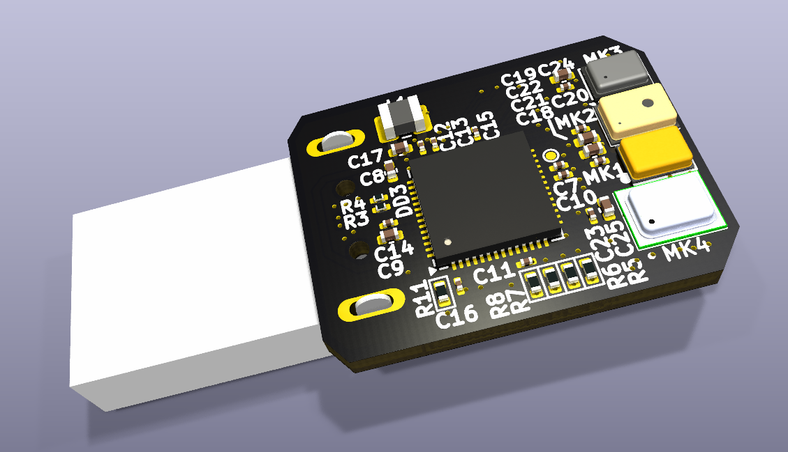
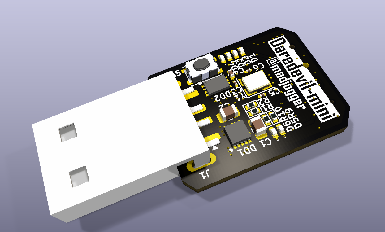
| Qty | Value | Footprint | References |
|---|---|---|---|
| 13 | 100nF | Capacitor_SMD:C_0201_0603Metric | C3, C7, C10, C11, C12, C13, C14, C15, C16, C18, C19, C20, C23 |
| 8 | 2.2uF | Capacitor_SMD:C_0402_1005Metric | C4, C8, C9, C17, C21, C22, C24, C25 |
| 6 | 300R | PCM_Resistor_SMD_AKL:R_0402_1005Metric | R5, R6, R7, R8, R9, R10 |
| 6 | LED | LED_SMD:LED_0402_1005Metric | D1, D2, D3, D4, D5, D6 |
| 2 | 100K | PCM_Resistor_SMD_AKL:R_0402_1005Metric | R1, R2 |
| 2 | 15pF | Capacitor_SMD:C_0201_0603Metric | C5, C6 |
| 2 | 27R | Resistor_SMD:R_0201_0603Metric | R3, R4 |
| 2 | 47uF | Capacitor_SMD:C_0805_2012Metric | C1, C2 |
| 1 | 1K | PCM_Resistor_SMD_AKL:R_0402_1005Metric | R11 |
| 1 | 2.2uH | Inductor_SMD:L_1008_2520Metric | L1 |
| 1 | ABM8-272-T3 | Crystal:Crystal_SMD_3225-4Pin_3.2x2.5mm | Y1 |
| 1 | INMP441ACEZ-R7 | INMP441:INMP441 | MK4 |
| 1 | KMR221GLFS | Button_Switch_SMD:SW_SPST_PTS810 | SW1 |
| 1 | MP23DB01HPTR | MP23DB01HPTR:MP23DB01HPTR | MK1 |
| 1 | MP34DT01TR-M | MP34DT01:MP34DT01 | MK2 |
| 1 | RP2040 | Package_DFN_QFN:QFN-56-1EP_7x7mm_P0.4mm_EP3.2x3.2mm | DD3 |
| 1 | RT6150B-33GQW | RT6150B-33GQW:RT6150B-33GQW | DD1 |
| 1 | SPH0645LM4H | Sensor_Audio:Knowles_SPH0645LM4H-6_3.5x2.65mm | MK3 |
| 1 | TestPoint 1mm | TestPoint:TestPoint_Pad_D1.0mm | TP1 |
| 1 | USB_A | Connector_USB:USB_A_Connfly_DS1098_Horizontal | J1 |
| 1 | W25Q16JVUXIQ_TR | W25Q16JVUXIQ:W25Q16JVUXIQ | DD2 |
Madjogger1202/Madpad
Custom macropad based on RP2040 with display, audio feedback, and per-key RGB lighting.


7west/PicoTop
A very basic computer & OS based on the RP2350 microcontroller

SCREAM325/TI_INFINITY
contains PCB file for PCBway and GCODE files for speaker case.


AllenNeuralDynamics/harp.device.lickety-split
0360: an ephys-compliant capacitive lick detector

EmielV2002/Inputshaper-PCB
A PCB to automatically tune your inputshaper settings.
It measures 23 × 17.6 mm and has 2 copper layers, 1.6 mm thick.
54 parts, built around the RP2040, RT6150B-33GQW, ABM8-272-T3 and INMP441ACEZ-R7. The full list of its parts is on this page, with links to each part's symbol and footprint where PCBKit's library has them.
From the Madjogger1202/Daredevil-mini repository on GitHub, at the commit this page was made from: the board is Daredevil-mini.kicad_pcb and its schematic Daredevil-mini.kicad_sch. PCBKit opens the board in the browser, with nothing to install.
Its repository states no licence, so its author keeps all rights: ask Madjogger1202 before reusing the design.