6 layers50 × 23 mm
Esp32p4amoled3.19
v-cu/dpf-load-monitor-wide
ESP32-P4 diagnostic display for VAG diesels — live DPF and engine data over CAN (UDS) on a 3.19" ultra-wide AMOLED. Firmware, KiCad files, BOM and 3D enclosure.
115 parts12

 madcow4242/Arduino-Ornament
Arduino ATTiny414 (814/1614/424/824/1624/3224) powered 30-LED programmable Christmas Ornament (or badge, etc.)
Ornament is an open-source printed circuit board by madcow4242, from the madcow4242/Arduino-Ornament repository on GitHub. It is a 2-layer board of 98.9 × 117.7 mm with 55 parts on 28 nets, routed with 373 tracks and 110 vias.
It is built around the ATTINY414-SSN and TEMT6200FX01. Its parts include 30 diodes, 11 resistors, 4 capacitors, 2 ICs and 2 connectors. It belongs with the lEDs and displays boards and the AVR (ATmega, ATtiny) boards of this library.


A custom LED Christmas ornament with advent calendar functionality, built using Arduino and KiCad. This project can easily be adapted to other formats such as a badge by changing the PCB layout.
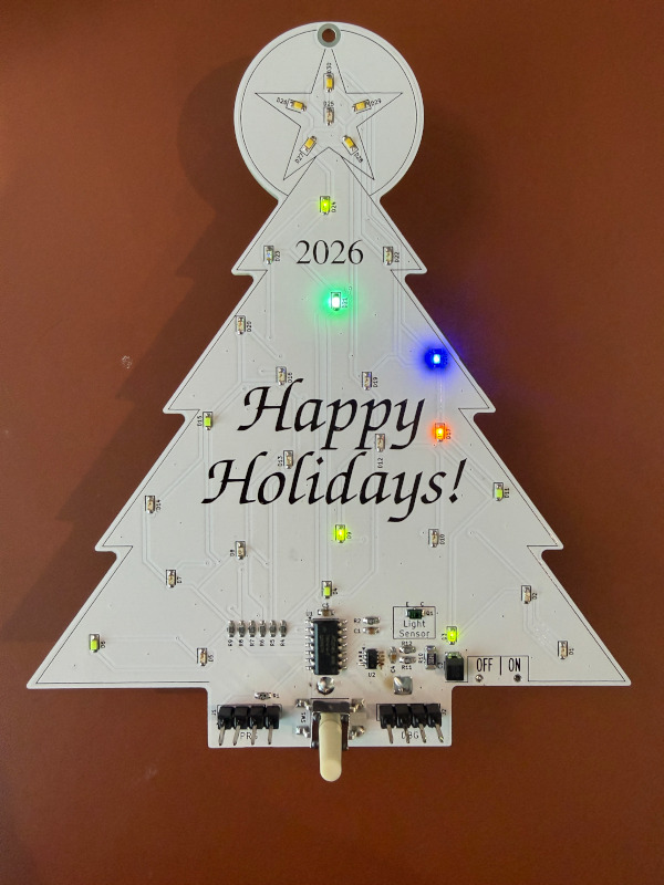
This project is organized into three main directories:
KiCad_PCB_Ornament/)Contains all KiCad design files for the PCB:
The PCB layout can be easily customized with your own text, or into a different physical format or size (like a badge) using KiCad - however if modifying the layout you'll have to re-route the board as well of course. I chose to put the control electronics on the front of the board (to be geeky), but they could easily be moved to the back to clean up the appearance.
NOTE: the board design includes optional current monitoring circuit and light sensing circuit. Neither of these are implemented in the production software, however they are fully functional and usable in the test software. Those features can be ported to production as needed, or removed or unpopulated on the PCB.
Ornament_production_1/)The main firmware for the ornament controller:
Ornament_production_1.ino)Ornament_test_1/)Code for testing and validating the PCB functionality:
This project is licensed under the MIT License - see the LICENSE file for details.
| Qty | Value | Footprint | References |
|---|---|---|---|
| 30 | LED | LED_SMD:LED_0603_1608Metric_Pad1.05x0.95mm_HandSolder | D1, D2, D10, D11, D12, D13, D14, D15, D16, D17, D18, D19, D20, D21, D22, D23 +14 |
| 6 | R82 | Resistor_SMD:R_0603_1608Metric_Pad0.98x0.95mm_HandSolder | R4, R5, R6, R7, R8, R9 |
| 2 | Conn_01x04_Pin | Connector_PinHeader_2.54mm:PinHeader_1x04_P2.54mm_Vertical | J1, J2 |
| 2 | R100 | Resistor_SMD:R_0603_1608Metric_Pad0.98x0.95mm_HandSolder | R11, R12 |
| 1 | ATtiny414-SS | Package_SO:SOIC-14_3.9x8.7mm_P1.27mm | U1 |
| 1 | Battery_Cell | CustomLibrary:BatteryHolder_Keystone_2479_3xAAA-NoHoles | BT1 |
| 1 | C10nF | Capacitor_SMD:C_0603_1608Metric_Pad1.08x0.95mm_HandSolder | C1 |
| 1 | C1nF | Capacitor_SMD:C_0603_1608Metric_Pad1.08x0.95mm_HandSolder | C4 |
| 1 | C1uF | Capacitor_SMD:C_0603_1608Metric_Pad1.08x0.95mm_HandSolder | C5 |
| 1 | C220uF or 470uF low-ESR Polymer or Tantalum | Capacitor_SMD:C_1210_3225Metric_Pad1.33x2.70mm_HandSolder | C3 |
| 1 | INA190A3IDDFR | Package_TO_SOT_SMD:SOT-23-8_Handsoldering | U2 |
| 1 | MountingHole | MountingHole:MountingHole_2.2mm_M2_DIN965_Pad_TopBottom | H1 |
| 1 | QR Code (silkscreen) | CustomLibrary:15mmQR_cazabon_ornament | H2 |
| 1 | R1 | Resistor_SMD:R_1206_3216Metric | R10 |
| 1 | R10k | Resistor_SMD:R_0603_1608Metric_Pad0.98x0.95mm_HandSolder | R2 |
| 1 | R4.7k | Resistor_SMD:R_0603_1608Metric_Pad0.98x0.95mm_HandSolder | R1 |
| 1 | SW_Push | Button_Switch_SMD:SW_Push_1P1T_NO_E-Switch_TL3301NxxxxxG | SW1 |
| 1 | SW_SPDT | Switch:CSS1210TB | SW2 |
| 1 | TEMT6200FX01 | Resistor_SMD:R_0805_2012Metric_Pad1.20x1.40mm_HandSolder | Q1 |
v-cu/dpf-load-monitor-wide
ESP32-P4 diagnostic display for VAG diesels — live DPF and engine data over CAN (UDS) on a 3.19" ultra-wide AMOLED. Firmware, KiCad files, BOM and 3D enclosure.

kkrzysztofik/Anyka_ak3918_hacking_journey
Reverse engineering and hacking journey for Chinese IP cameras based on Anyka AK3918 SoC

xx0x/sw63
Sci-fi inspired electronic watch. MK4 currently in the development (out in 2026).


GerardZ/AFLII
This is a replacement for the PCF8574 LCD-interface board, which is pin but not API compatible.

Quard/7clock
Simple budget clock using 7 segment display with cheap PIC microcontroller and RTC chip

It measures 98.9 × 117.7 mm and has 2 copper layers, 1.6 mm thick.
55 parts, built around the ATTINY414-SSN and TEMT6200FX01. The full list of its parts is on this page, with links to each part's symbol and footprint where PCBKit's library has them.
From the madcow4242/Arduino-Ornament repository on GitHub, at the commit this page was made from: the board is KiCad_PCB_Ornament/Ornament.kicad_pcb and its schematic KiCad_PCB_Ornament/Ornament.kicad_sch. PCBKit opens the board in the browser, with nothing to install.
Its repository states no licence, so its author keeps all rights: ask madcow4242 before reusing the design.