4 layers293.6 × 143.3 mm
 macdems/NixieClock
A compact IN-14 Nixie clock project with both vintage character and modern connectivity.
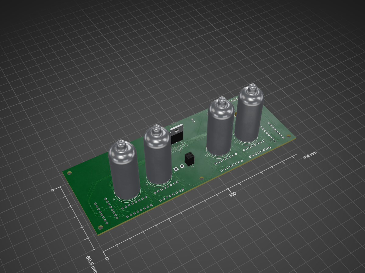
NixieClock is an open-source printed circuit board by macdems, from the macdems/NixieClock repository on GitHub, published under the CC-BY-SA-4.0 licence. It is a 2-layer board of 164 × 60.5 mm with 48 parts on 105 nets, routed with 535 tracks and 29 vias.
It is built around the LM2596T-5.0, 74HC595 and MMBTA44, with the WS2812B, SS24 and ES1G among its other parts. Its parts include 9 ICs, 9 transistors, 7 diodes, 6 resistors and 2 capacitors. It belongs with the lEDs and displays boards and the ESP32 and RISC-V boards of this library.


A connected IN-14 Nixie tube clock combining classic display technology with modern embedded control.
This repository contains the complete project: firmware, electrical schematic, PCB design, and case design.
The project is built around an ESP-based controller and drives IN-14 Nixie tubes to display time with network-connected features such as:
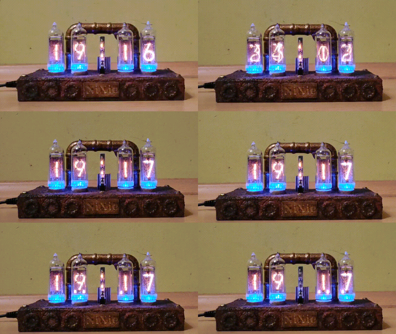
This project is designed for IN-14 Nixie tubes and includes the supporting electronics required for:
| Ref | Qty | Value | Description |
|---|---|---|---|
| C1 | 1 | 220µF/35V | electrolytic capacitor THT radial D5.0mm P2.50mm |
| C2 | 1 | 220µF | electrolytic capacitor THT radial D5.0mm P2.50mm |
| D1, D2, D3, D4 | 4 | WS2812B | WS2812B-1209 SMD mount LED |
| D5, D7 | 2 | SS24 | SMA package |
| D6 | 1 | ES1G | SMA package |
| HS1 | 1 | T8WC | heatsink for for TO-220 (https://aliexpress.com/item/1005006082544471.html) |
| J1 | 1 | 12V | 01x02 screw terminal P5.08mm |
| J2 | 1 | 180V | 01x02 screw terminal P5.08mm |
| L1 | 1 | 150mH | SMD inductor L_10.4x10.4 H4.8 |
| N1, N2, N3, N4 | 4 | IN-14 | Nixie IN-14 |
| N5 | 1 | 02×02 pin socket P2.54mm | |
| N5 | 1 | Nixie colon separator (https://aliexpress.com/item/1005009385409998.html) | |
| Q1, Q2, Q3, Q4, Q5, Q6, Q7, Q8, Q9 | 9 | MMBTA44 | SOT-23 package |
| R1, R2, R3, R4 | 4 | 12k | 1026 SMD |
| R5, R6 | 2 | 390k | 1026 SMD |
| U1, U2, U3, U4 | 4 | SN74141N | DIP-16 W7.62mm |
| U5, U6, U7 | 3 | 74HC595 | DIP-16 W7.62mm |
| U8 | 1 | LM2596T-5 | TO-220-5 |
| U9 | 1 | ESP32-C3 Super Mini | |
| 1 | NCH6100HV | high voltage DC power supply for Nixie tubes | |
| 6 | M3×5×4 | brass insert M3 H5mm OD4mm | |
| 2 | M2.5×3×3.5 | brass insert M2.5 H3mm OD3.5mm | |
| 1 | DC022B | DC power jack supply socket (https://aliexpress.com/item/1005005583190148.html) |
Firmware is based on ESP-IDF. First you need to configure it, specyfying your WiFi and MQTT creedentials. Then you can build and flash the firmware with:
idf.py build
idf.py -p <PORT> flash monitor
Configuration can be adjusted with:
idf.py menuconfigmain/ ESP-IDF application sources
PCB/ PCB layout and fabrication files
NixieClock.FCStd FreeCAD case design file
NixieClock.3mf Case design export for 3D printingNixie clocks operate with high voltage. Hardware assembly, probing, and testing should be performed carefully and only with appropriate experience.
This project is licensed under the Creative Commons Attribution-ShareAlike 4.0 International (CC BY-SA 4.0) license.
See the LICENSE.md file for full license text.
This repository is intended as a complete source package for building an IN-14 Nixie clock from electronics to enclosure.
A compact Nixie clock project with both vintage character and modern connectivity.
| Qty | Value | Footprint | References |
|---|---|---|---|
| 9 | MMBTA44 | Package_TO_SOT_SMD:SOT-23_Handsoldering | Q1, Q2, Q3, Q4, Q5, Q6, Q7, Q8, Q9 |
| 6 | MountingHole | MountingHole:MountingHole_3.2mm_M3 | H1, H2, H3, H4, H5, H6 |
| 4 | 12k | Resistor_SMD:R_1206_3216Metric_Pad1.30x1.75mm_HandSolder | R1, R2, R3, R4 |
| 4 | IN-14 | Nixies:IN-14 | N1, N2, N3, N4 |
| 4 | SN74141N | Package_DIP:DIP-16_W7.62mm | U1, U2, U3, U4 |
| 4 | WS2812B | Custom:LED-SMD_4P-L3.2-W2.7-TL-WS2812B-1209 | D1, D2, D3, D4 |
| 3 | 74HC595 | Package_DIP:DIP-16_W7.62mm | U5, U6, U7 |
| 2 | 390k | Resistor_SMD:R_1206_3216Metric_Pad1.30x1.75mm_HandSolder | R5, R6 |
| 2 | SS24 | Diode_SMD:D_SMA_Handsoldering | D5, D7 |
| 1 | 12V | TerminalBlock:TerminalBlock_bornier-2_P5.08mm | J1 |
| 1 | 150mH | Inductor_SMD:L_10.4x10.4_H4.8 | L1 |
| 1 | 180V | TerminalBlock:TerminalBlock_bornier-2_P5.08mm | J2 |
| 1 | 220µF | Capacitor_THT:CP_Radial_D5.0mm_P2.50mm | C2 |
| 1 | 220µF/35V | Capacitor_THT:CP_Radial_D5.0mm_P2.50mm | C1 |
| 1 | ES1G | Diode_SMD:D_SMA_Handsoldering | D6 |
| 1 | ESP32-C3_SUPERMINI_TH | ESP32-C3_SUPERMINI:MODULE_ESP32-C3_SUPERMINI_TH | U9 |
| 1 | Heatsink | Custom:Heatsink_T8WC_TO-220 | HS1 |
| 1 | LM2596T-5 | Package_TO_SOT_THT:TO-220-5_P3.4x3.7mm_StaggerOdd_Lead3.8mm_Vertical | U8 |
| 1 | ~ | Connector_PinSocket_2.54mm:PinSocket_2x02_P2.54mm_Vertical | N5 |
It measures 164 × 60.5 mm and has 2 copper layers, 1.6 mm thick.
48 parts, built around the LM2596T-5.0, 74HC595, MMBTA44 and WS2812B. The full list of its parts is on this page, with links to each part's symbol and footprint where PCBKit's library has them.
From the macdems/NixieClock repository on GitHub, at the commit this page was made from: the board is PCB/NixieClock.kicad_pcb and its schematic PCB/NixieClock.kicad_sch. PCBKit opens the board in the browser, with nothing to install.
Its repository publishes it under the CC-BY-SA-4.0 licence: you may reuse it on that licence's terms (keep the author's notice, and for a copyleft licence share your changes alike).


olincollege/olin-eclipse-ballooning
Olin's National Eclipse Ballooning Project team repository


macdems/ESPHome-OpenTherm-Gateway
Firmware ESPHome + własny komponent + sprzęt (PCB + obudowa) dla ESP8266 (Wemos D1 mini) działający jako bramka / monitor OpenTherm między kotłem a termostatem z integracją Home Assistant.


