

2 layers69.1 × 77.1 mm

 lzyang2000/PCB-Projects1
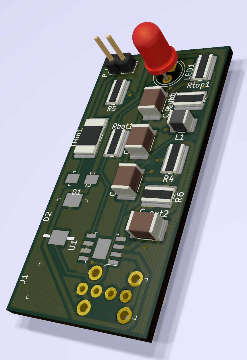
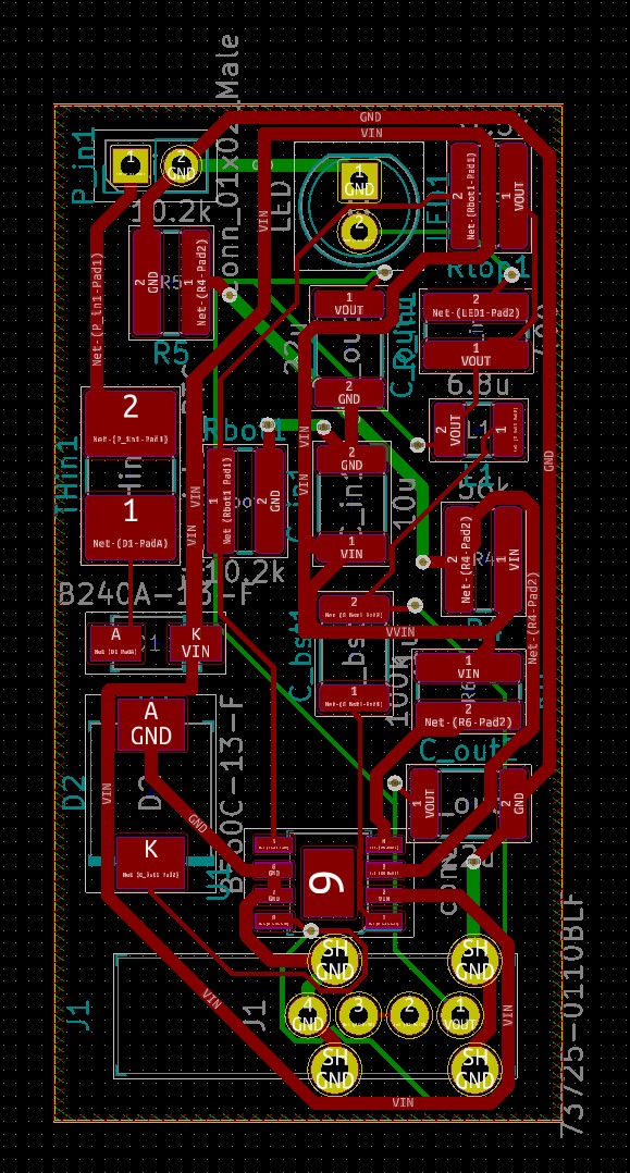
USB Charger is an open-source printed circuit board by lzyang2000, from the lzyang2000/PCB-Projects repository on GitHub. It is a 2-layer board of 25.4 × 50.8 mm with 18 parts on 12 nets, routed with 195 tracks and 16 vias.
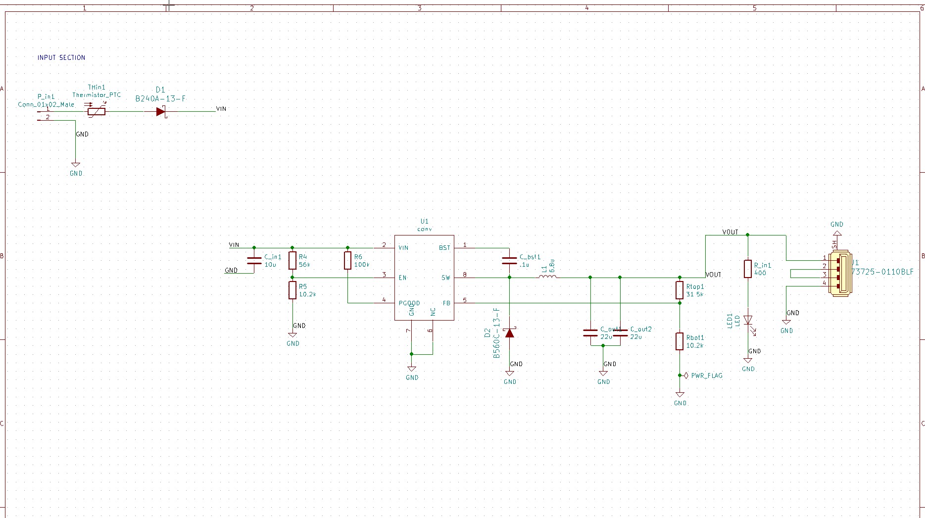
It is built around the 73725-0110BLF and B560C-13-F-MS. Its parts include 4 resistors, 3 diodes, 1 IC, 1 connector and 1 inductor. It belongs with the power boards of this library.
Takes input of 9-18V DC and outputs power compliant with USB Battery Charging 1.2.
BOM
| Qty | Value | Footprint | References |
|---|---|---|---|
| 2 | 10.2k | Resistor_SMD:R_1020_2550Metric_Pad1.33x5.20mm_HandSolder | R5, Rbot1 |
| 2 | 22u | Capacitor_SMD:C_1812_4532Metric_Pad1.30x3.40mm_HandSolder | C_out1, C_out2 |
| 1 | .1u | Capacitor_SMD:C_1812_4532Metric_Pad1.30x3.40mm_HandSolder | C_bst1 |
| 1 | 100k | Resistor_SMD:R_1020_2550Metric_Pad1.33x5.20mm_HandSolder | R6 |
| 1 | 10u | Capacitor_SMD:C_1812_4532Metric_Pad1.30x3.40mm_HandSolder | C_in1 |
| 1 | 31.5k | Resistor_SMD:R_1020_2550Metric_Pad1.33x5.20mm_HandSolder | Rtop1 |
| 1 | 400 | Resistor_SMD:R_1020_2550Metric_Pad1.33x5.20mm_HandSolder | R_in1 |
| 1 | 56k | Resistor_SMD:R_1020_2550Metric_Pad1.33x5.20mm_HandSolder | R4 |
| 1 | 6.8u | Inductor_SMD:L_1210_3225Metric_Pad1.42x2.65mm_HandSolder | L1 |
| 1 | 73725-0110BLF | digikey-footprints:USB_A_Female_Vertical_RA_73725-0110BLF | J1 |
| 1 | B240A-13-F | digikey-footprints:DO-214AC | D1 |
| 1 | B560C-13-F | digikey-footprints:DO-214AB | D2 |
| 1 | Conn_01x02_Male | Connector_PinHeader_2.54mm:PinHeader_1x02_P2.54mm_Vertical | P_in1 |
| 1 | LED | LED_THT:LED_D5.0mm | LED1 |
| 1 | Thermistor_PTC | Resistor_SMD:R_2816_7142Metric_Pad3.20x4.45mm_HandSolder | THin1 |
| 1 | conv | digikey-footprints:SOIC-8-1EP_W3.9mm | U1 |


martinribelotta/h7dragonman
STM32H7 board for industrial protocol bridge


CodeLinaro-mirror/qcomlt_debugboard
96boards specifications compliant Mezzanine used to control the DC Input, USB VBUS, PWR/RST buttons and Debug UART via a single USB2.0 CDC interface.


bryce-builds/PiGarage
Open-source Raspberry Pi power management and audio HAT for automotive head-unit use

diegodemarco/cog1
cog1 is an open-source industrial IoT gateway (hardware and software) built as a motherboard hosting an Orange Pi Zero 3 Linux SBC.
It measures 25.4 × 50.8 mm and has 2 copper layers, 1.6 mm thick.
18 parts, built around the 73725-0110BLF and B560C-13-F-MS. The full list of its parts is on this page, with links to each part's symbol and footprint where PCBKit's library has them.
From the lzyang2000/PCB-Projects repository on GitHub, at the commit this page was made from: the board is USB-Charger/Untitled.kicad_pcb. PCBKit opens the board in the browser, with nothing to install.
Its repository states no licence, so its author keeps all rights: ask lzyang2000 before reusing the design.