2 layers100 × 80 mm
Brewingstation3
Gr3yh0und/brewingstation
Automate your brew day: ESP32 + induction cooktop + PID control, talking MQTT to CraftBeerPi.
51 parts1MIT

 lysek01/max31865_stack
A stackable carrier board for the Adafruit MAX31865 RTD-to-digital converter. Each board hosts up to 8 MAX31865 modules and multiple boards can be stacked on brass standoffs to scale the channel count without changing…
Max31865 stack is an open-source printed circuit board by lysek01, from the lysek01/max31865_stack repository on GitHub, published under the MIT licence. It is a 2-layer board of 245.2 × 48.2 mm with 33 parts on 67 nets, routed with 296 tracks and 138 vias.
It is built around the MAX31865AAP+ and PCF8574T. Its parts include 10 connectors, 9 ICs, 5 resistors and 2 capacitors.


A stackable carrier board for the Adafruit MAX31865 RTD-to-digital converter. Each board hosts up to 8 MAX31865 modules and multiple boards can be stacked on brass standoffs to scale the channel count without changing the wiring to the host.
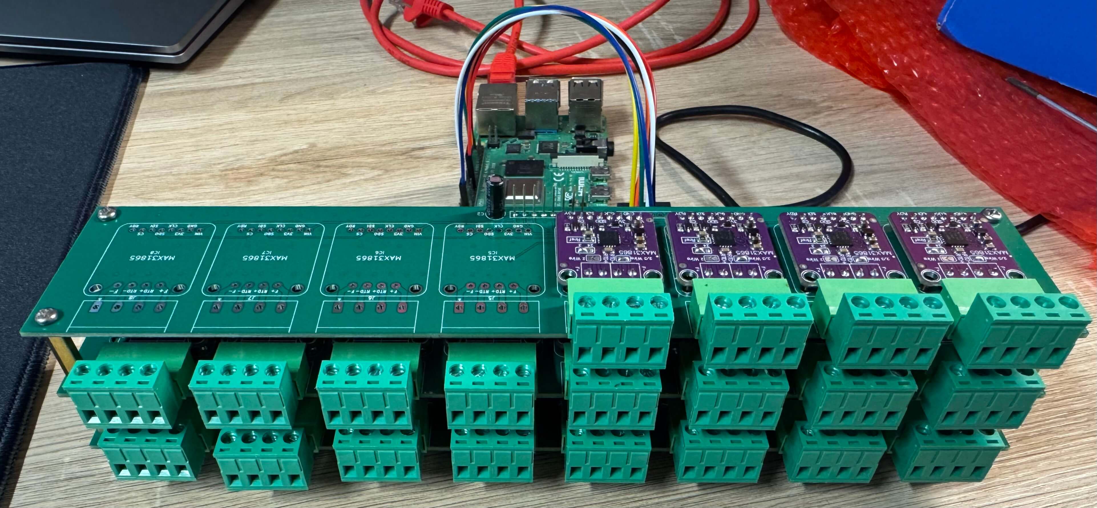
Each MAX31865 from Adafruit is an excellent PT100/PT1000 front-end, but wiring more than a handful of them by hand is tedious and error-prone — every module needs power, an SPI bus and its own chip-select line.
This project solves that with a carrier PCB that:
With the default I2C address range (0x20–0x27) the stack supports up to 8 boards = 64 RTD channels from a single Raspberry Pi.
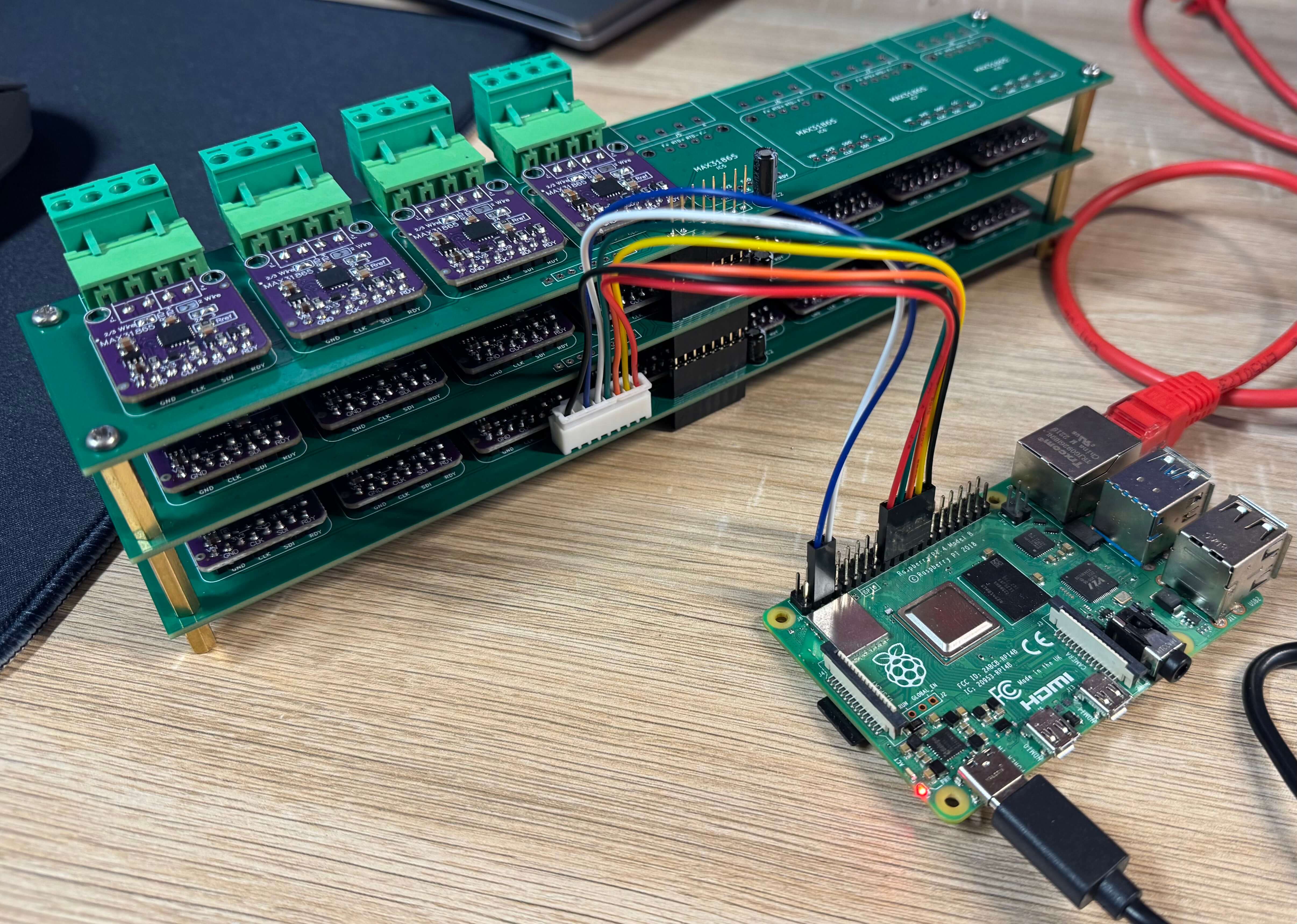
                              JST XH 8-pin
                                   │
                                   ▼
  Raspberry Pi ──── Board #1 (bottom) ──┐
                    Board #2            │  stacked through
                    Board #N            │  pass-through pin headers
                    ──────────────────  ┘  (I2C + SPI + power)
                         │
        ┌────────────────┼────────────────┐
        ▼                ▼                ▼
     PCF8574          PCF8574          PCF8574
      0x25             0x26             0x27
        │                │                │
        ▼                ▼                ▼
     8x CS            8x CS            8x CS
        │                │                │
        ▼                ▼                ▼
    8x MAX31865      8x MAX31865      8x MAX31865

  SPI bus (SCK, MOSI, MISO) is shared across every MAX31865 on every board.
  CS for each module is driven by one PCF8574 output.
The PCF8574 expander on each board takes the I2C address selected by the
jumpers JP1 / JP2 / JP3 (PCF8574 address bits A0/A1/A2). This is how
each board in the stack gets its own unique address — and therefore its own
set of 8 chip-select lines.
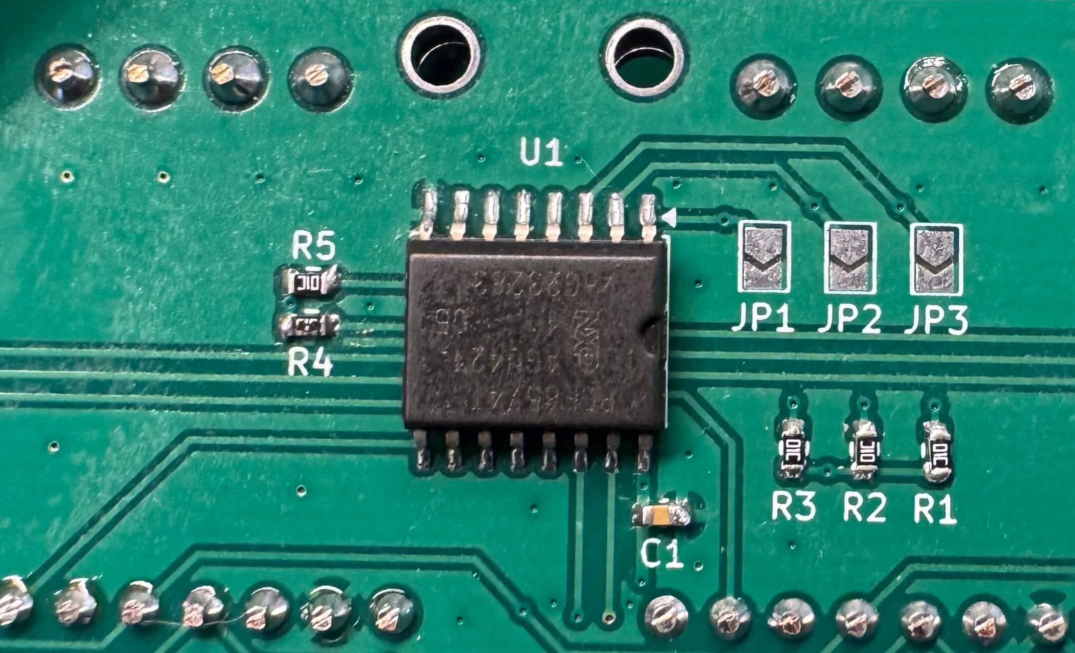
| Reference | Part |
|---|---|
| U1 | PCF8574 I2C 8-bit I/O expander (SOIC-16) |
| 8x | Sockets for Adafruit MAX31865 PT100/PT1000 breakout |
| 8x | 4-pin pluggable terminal blocks (5.08 mm, RTD sensor) |
| JP1–JP3 | I2C address jumpers (A0, A1, A2) |
| J1 | 8-pin JST XH connector (host link, populated on bottom board only) |
| — | 8-pin stackable pin headers — bus pass-through between boards |
Boards stack mechanically on brass M3 standoffs and electrically through stackable 8-pin pin headers, which pass the I2C, SPI and power signals straight up through the stack.
The bottom board carries the 8-pin JST XH connector (J1) that is wired to the Raspberry Pi. Any boards above it inherit the same bus through the pass-through headers — no extra cabling is needed when adding a board.
Each board only needs a unique PCF8574 address, set with the three address
jumpers (JP1/JP2/JP3).
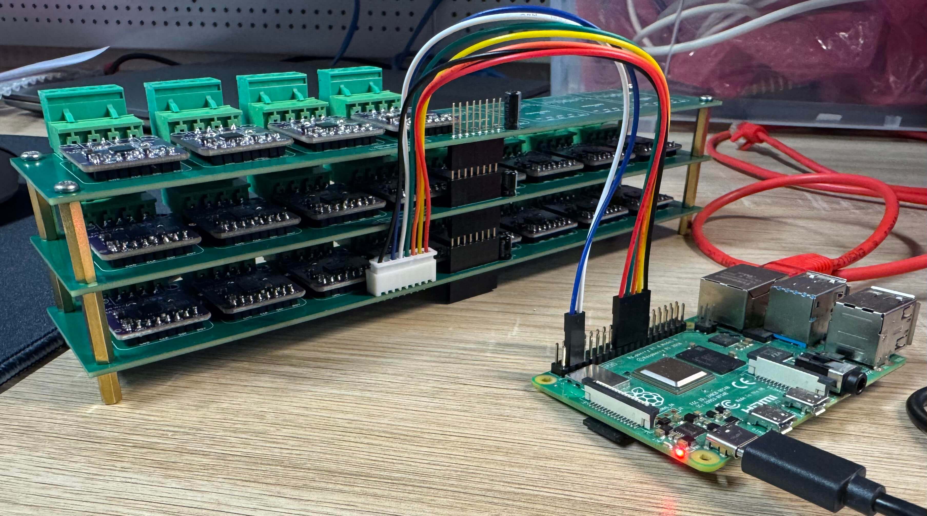
Each channel exposes a 4-pin pluggable terminal block matching the Adafruit MAX31865 module pinout. Use the Adafruit module's own solder jumpers to configure 2-, 3- or 4-wire mode.
⚠️ Use a reference resistor matched to your RTD:
- PT100 → 430 Ω (default on Adafruit boards)
- PT1000 → 4300 Ω
Mixing PT1000 sensors with the default 430 Ω reference (or vice versa) will not work correctly.
The bottom board of the stack carries an 8-pin JST XH connector (J1) that links the whole stack to the Raspberry Pi. Each pin of the connector is labelled on the board's silkscreen — wire each labelled signal to the matching Raspberry Pi GPIO header pin according to the table below.
The diagram below highlights the relevant pin groups on the 40-pin header: the I²C group (SDA / SCL) and the SPI group (MOSI / MISO / SCLK, together with the 3V3 and GND pins that are convenient to use for powering the stack).
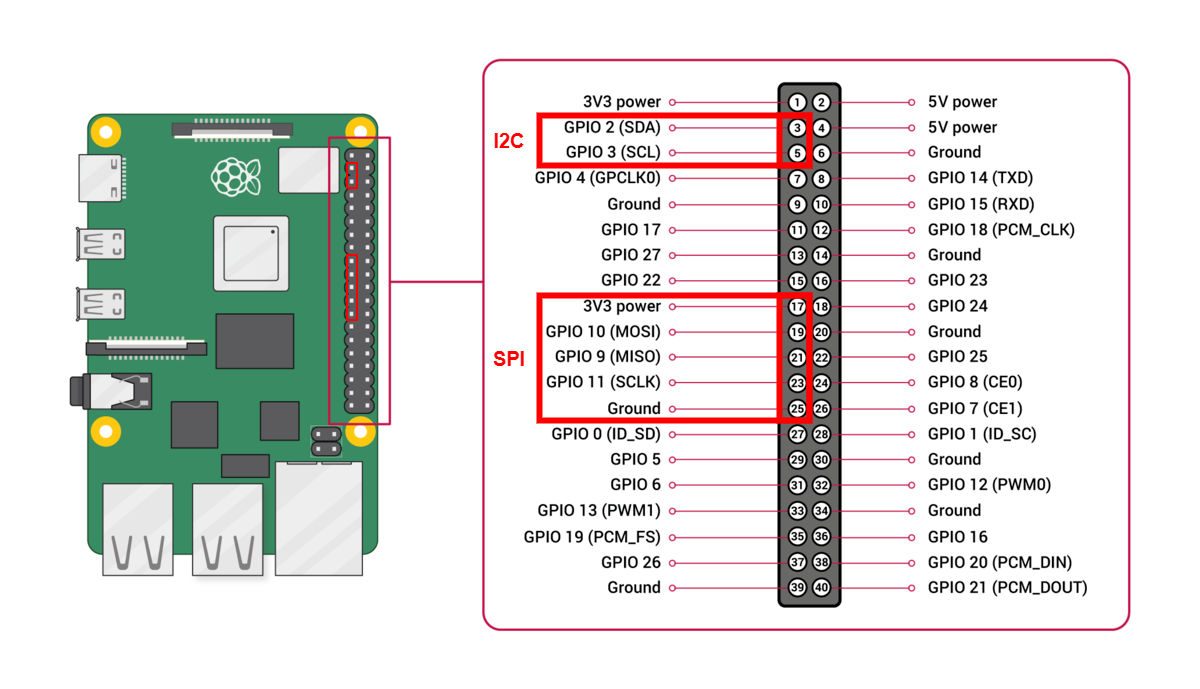
Counting from the left edge of the JST XH connector (pin 1) to the right (pin 8):
| JST pin | Silkscreen | Function | RPi physical pin | RPi BCM GPIO |
|---|---|---|---|---|
| 1 | GND | Ground | 6 | — |
| 2 | GND | Ground (redundant) | any GND | — |
| 3 | SDA | I²C data (PCF8574) | 3 | GPIO 2 |
| 4 | SCL | I²C clock (PCF8574) | 5 | GPIO 3 |
| 5 | MOSI | SPI MOSI (MAX31865) | 19 | GPIO 10 |
| 6 | MISO | SPI MISO (MAX31865) | 21 | GPIO 9 |
| 7 | CLK | SPI clock (MAX31865) | 23 | GPIO 11 |
| 8 | VCC | Logic supply | 1 (3V3) | — |
Both GND pins on the connector (pins 1 and 2) are tied to the same ground
net on the board. In practice you only need to wire one of them on your
cable — the other can be left unconnected or used as a spare.
ℹ️ The Adafruit MAX31865 breakout accepts 3 V–5 V on
VIN, but its logic level must matchVIN. When wiring to a Raspberry Pi (3.3 V GPIO), power the stack from the Pi's 3V3 pin — that keepsVCCand the SPI / I²C logic at the same level and matches the GPIO directly without a level shifter.
ℹ️ The "RPi physical pin" column uses the 1–40 header numbering printed on Raspberry Pi pinout cards. "BCM GPIO" is the numbering reported by
pinoutand used in/sys/class/gpio. Both refer to the same physical pad; pick whichever is more convenient.
When more than one board is in the stack, the same signals propagate upwards through the stackable pin headers — only this single JST cable goes to the Pi.
A reference reader is provided in software/read.py.
It runs on Linux (tested on Raspberry Pi OS) and:
software/requirements.txt:
pip install -r software/requirements.txtBoth buses are disabled by default on a fresh Raspberry Pi OS image. Enable
them with raspi-config:
sudo raspi-configThen navigate to Interface Options → I2C → Enable and Interface Options → SPI → Enable, and reboot.
After the reboot you should see the devices in /dev:
ls /dev/i2c-* /dev/spidev*
# /dev/i2c-1  /dev/spidev0.0  /dev/spidev0.1
A quick sanity check that the boards are visible on the I2C bus:
sudo apt install i2c-tools
i2cdetect -y 1
You should see the PCF8574 expanders show up in the 0x20–0x27 range — one address per board in the stack.
Open software/read.py and adjust the constants at the
top of the file:
| Constant | Meaning |
|---|---|
I2C_BUS | I2C bus index (1 on Raspberry Pi) |
SPI_BUS/SPI_DEVICE | SPI bus/CS index used to talk to the modules |
SPI_SPEED_HZ | SPI clock; 100 kHz is conservative and reliable |
THREE_WIRE | True for 3-wire RTDs, False for 2/4-wire |
FILTER_50HZ | True in 50 Hz mains regions, False for 60 Hz |
RNOMINAL | 100.0 for PT100, 1000.0 for PT1000 |
DEFAULT_RREF | Reference resistor on the Adafruit module (430 / 4300 Ω) |
PRINT_INTERVAL | Seconds between measurement scans |
python3 software/read.pyExample output:
MAX31865 multi-board reader
==========================
I2C bus:       1
SPI bus/dev:   0.0
...

Scanning for PCF8574 expanders...
  expander found: 0x25
  expander found: 0x26
  expander found: 0x27

Detecting MAX31865 modules behind each CS pin...
Expander 0x25:
  P0: MAX31865 OK      CONFIG OK 0x91, marker OK
  ...

============================================================
2026-05-15 14:23:01
CH00 E0x25-P0: OK        23.451 C   R=109.123 Ohm   raw=8412
CH01 E0x25-P1: OK        23.802 C   R=109.260 Ohm   raw=8423
...
scan time: 142.318 ms OK=24 NOT_OK=0.
├── assets/ photos of the assembled stack
├── hardware/ KiCad project (schematic, PCB) + JLCPCB production files
├── software/ Python reader for Raspberry Pi
├── LICENSE MIT
└── README.md you are hereReleased under the MIT License. The Adafruit MAX31865 module is a separate product; consult Adafruit's own documentation and licensing for the module itself.
Martin Lysek — 2026.
| Qty | Value | Footprint | References |
|---|---|---|---|
| 8 | Conn_01x04_Pin | Connector_Phoenix_MSTB:PhoenixContact_MSTBA_2,5_4-G-5,08_1x04_P5.08mm_Horizontal | J1, J2, J3, J4, J5, J6, J7, J8 |
| 8 | MAX31865 | kicad-footprint-collection:Adafruit_MAX31865 | IC1, IC2, IC3, IC4, IC5, IC6, IC7, IC8 |
| 4 | MountingHole | MountingHole:MountingHole_3.2mm_M3 | H1, H2, H3, H4 |
| 3 | 10k | Resistor_SMD:R_0603_1608Metric | R1, R2, R3 |
| 3 | SolderJumper_2_Open | Jumper:SolderJumper-2_P1.3mm_Open_TrianglePad1.0x1.5mm | JP1, JP2, JP3 |
| 2 | 4.7k | Resistor_SMD:R_0603_1608Metric | R4, R5 |
| 2 | Conn_01x08_Pin | Connector_PinHeader_2.54mm:PinHeader_1x08_P2.54mm_Vertical | J9, J10 |
| 1 | 100n | Capacitor_SMD:C_0603_1608Metric | C1 |
| 1 | 47u | Capacitor_THT:C_Radial_D5.0mm_H7.0mm_P2.00mm | C2 |
| 1 | PCF8574T | Package_SO:SOIC-16W_7.5x10.3mm_P1.27mm | U1 |
It measures 245.2 × 48.2 mm and has 2 copper layers, 1.6 mm thick.
33 parts, built around the MAX31865AAP+ and PCF8574T. The full list of its parts is on this page, with links to each part's symbol and footprint where PCBKit's library has them.
From the lysek01/max31865_stack repository on GitHub, at the commit this page was made from: the board is hardware/max31865_stack.kicad_pcb and its schematic hardware/max31865_stack.kicad_sch. PCBKit opens the board in the browser, with nothing to install.
Its repository publishes it under the MIT licence: you may reuse it on that licence's terms (keep the author's notice, and for a copyleft licence share your changes alike).
Gr3yh0und/brewingstation
Automate your brew day: ESP32 + induction cooktop + PID control, talking MQTT to CraftBeerPi.


jorticus/lupa-espresso
Espresso controller firmware for an E61-grouphead style espresso machine


DepBo/AquaCare
AquaCare là hệ thống theo dõi và quản lý nuôi trồng thủy sản, gồm ứng dụng web, ứng dụng di động và backend kết nối dữ liệu cảm biến với thiết bị trong ao/bể.

KozaMateusz/TemperatureManagementGUI
Graphical user interface to controll the temperature in a chamber.

N5GEH/n5geh.devices.iot_wa_aio
IoT-AIO is a wireless adapter for developing IoT applications for Industrial and Building Automation Systems based on the Espressif chipset ESP32.
