
2 layers68.6 × 53.3 mm
 lxdinh/Autonomous-Rover
Autonomous navigation rover featuring ESP32-S3 carrier board and I2C/SPI sensor integration
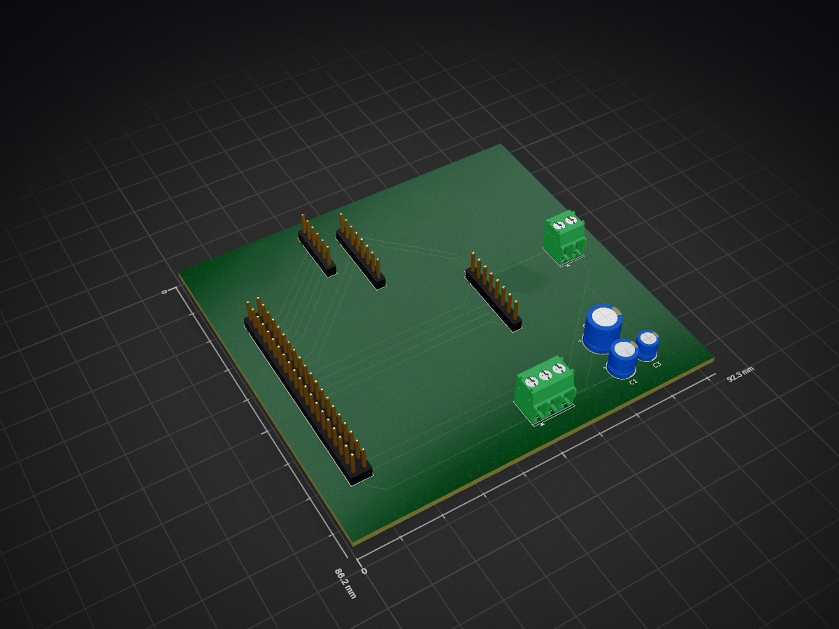
Autonomous Rover Kicad is an open-source printed circuit board by lxdinh, from the lxdinh/Autonomous-Rover repository on GitHub, published under the MIT licence. It is a 2-layer board of 92.3 × 86.2 mm with 9 parts on 44 nets, routed with 103 tracks and 0 vias.
It is built around the ESP32-S3. Its parts include 6 connectors and 3 capacitors. It belongs with the robots and motor control boards and the ESP32 boards of this library.




🏆 1st Place — UCSD ECE Design Competition (Nov–Dec 2025) · fastest pathfinding of 13 teams
Vision-guided autonomous ground rover on a custom ESP32-S3 PCB. An ArduCAM OV2640 camera runs on-board RGB565 obstacle detection, an MPU6050 IMU damps the heading, and an L298N H-bridge drives the wheels — coordinated by a lightweight FORWARD → STOP → AVOID state machine. Everything runs on the microcontroller.
hardware/.flowchart LR
subgraph Sensing
CAM[OV2640 camera<br/>SPI FIFO] --> DET[Red-blob detector<br/>RGB565, middle band]
IMU[MPU6050<br/>I2C] --> YAW[Yaw-rate filter]
end
DET --> SM[Nav state machine<br/>FORWARD / STOP / AVOID]
YAW --> MIX[Tank-drive mixer]
SM --> MIX
MIX --> MOT[L298N H-bridge<br/>LEDC PWM] --> W[Wheels]stateDiagram-v2
[*] --> FORWARD
FORWARD --> STOP: red band >= 20%
STOP --> AVOID: held 200 ms and still blocked
STOP --> FORWARD: obstacle cleared
AVOID --> FORWARD: blob out of viewAutonomous-Rover/
├── src/
│ ├── main.cpp # nav state machine + obstacle detection + cruise mixer
│ ├── Camera_SPI.h # ArduCAM OV2640 over SPI FIFO (DMA buffer, BMP/RGB565)
│ ├── Sensor_I2C.h # MPU6050 IMU (accel/gyro), bare-metal I2C
│ └── MotorDriver_PWM.h # L298N via ESP32 LEDC PWM (Arduino core 2.x/3.x aware)
├── include/memorysaver.h # ArduCAM camera-model selector (OV2640 Mini 2MP)
├── hardware/ # KiCad project, schematic (SVG), Gerbers
├── platformio.ini
└── README.md| Subsystem | Part | Interface |
|---|---|---|
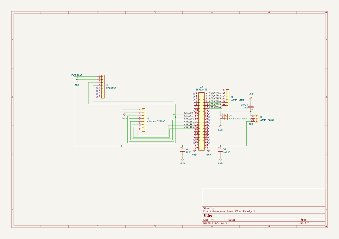
| MCU | ESP32-S3 (DevKitC-1 class) | — |
| Camera | ArduCAM OV2640 Mini 2MP | SPI FIFO + I²C control |
| IMU | MPU6050 (accel + gyro) | I²C @ 0x68 |
| Motor driver | L298N dual H-bridge | 6 GPIO (2 PWM enables + 4 direction) |
| Power | 9 V motor pack + 3.3 V logic | common ground |
| Function | GPIO | Function | GPIO | |
|---|---|---|---|---|
| L298N ENA — left PWM | 40 | I²C SDA | 15 | |
| L298N ENB — right PWM | 39 | I²C SCL | 17 | |
| L298N IN1 / IN2 — left dir | 44 / 43 | SPI SCK | 12 | |
| L298N IN3 / IN4 — right dir | 42 / 41 | SPI MISO | 13 | |
| Camera CS | 10 | SPI MOSI | 11 |
Each captured frame is RGB565 (one 16-bit value per pixel). The detector scans the middle horizontal third of the frame — where a head-on obstacle sits — and flags a pixel as "red" when:
| Channel | Bits | Rule |
|---|---|---|
| Red | 5 (0–31) | ≥ 22 |
| Green | 6 (0–63) | ≤ 14 |
| Blue | 5 (0–31) | ≤ 14 |
If ≥ 20 % of the band's pixels pass, the frame is treated as blocked and the
state machine reacts. All thresholds are compile-time constants in
src/main.cpp — retune RED_MIN_5BIT, GREEN_MAX_6BIT,
BLUE_MAX_5BIT, and DETECTION_THRESHOLD_PERCENT for your obstacle color and
lighting.
Built with PlatformIO (ESP32-S3 / Arduino
framework). The ArduCAM library is pulled from the PlatformIO registry
automatically; the camera model is selected via the -DOV2640_MINI_2MP build
flag in platformio.ini.
# from the repo root
pio run                        # compile
pio run -t upload              # flash (board on its native USB port)
pio device monitor -b 115200   # serial @ 115200
Arduino IDE users: install the ArduCAM library, provide a memorysaver.h
with #define OV2640_MINI_2MP, select an ESP32-S3 board with USB CDC On Boot:
Enabled, and build src/main.cpp.
MOTOR_MAX_DUTY_PCT (85 %) so that simultaneous
acceleration on a sagging 9 V pack does not brown out the 3.3 V logic rail.MIT — see LICENSE. Firmware and hardware authored for the UCSD ECE Design Competition.
| Qty | Value | Footprint | References |
|---|---|---|---|
| 1 | 100uF | Capacitor_THT:CP_Radial_D6.3mm_P2.50mm | C1 |
| 1 | 10uF | Capacitor_THT:CP_Radial_D5.0mm_P2.50mm | C3 |
| 1 | 470uF | Capacitor_THT:CP_Radial_D8.0mm_P3.50mm | C2 |
| 1 | 9V Battery Input | TerminalBlock_Phoenix:TerminalBlock_Phoenix_PT-1,5-2-3.5-H_1x02_P3.50mm_Horizontal | J4 |
| 1 | Arducam OV2640 | Connector_PinHeader_2.54mm:PinHeader_1x08_P2.54mm_Vertical | J2 |
| 1 | ESP32-S3 | Connector_PinHeader_2.54mm:PinHeader_2x20_P2.54mm_Vertical | J3 |
| 1 | L298N Logic | Connector_PinHeader_2.54mm:PinHeader_1x06_P2.54mm_Vertical | J5 |
| 1 | L298N Power | TerminalBlock_Phoenix:TerminalBlock_Phoenix_PT-1,5-3-3.5-H_1x03_P3.50mm_Horizontal | J6 |
| 1 | MPU6050 | Connector_PinHeader_2.54mm:PinHeader_1x08_P2.54mm_Vertical | J1 |


aeonSolutions/AeonLabs-AI-Volvo-MKII-Open-Hardware
Volvo MKII Open Hardware


lhm0/rotating_display_color
56 LED rotating color display with RP2040 and ESP32 microcontrollers
It measures 92.3 × 86.2 mm and has 2 copper layers, 1.6 mm thick.
9 parts, built around the ESP32-S3. The full list of its parts is on this page, with links to each part's symbol and footprint where PCBKit's library has them.
From the lxdinh/Autonomous-Rover repository on GitHub, at the commit this page was made from: the board is hardware/Autonomous Rover Kicad.kicad_pcb and its schematic hardware/Autonomous Rover Kicad.kicad_sch. PCBKit opens the board in the browser, with nothing to install.
Its repository publishes it under the MIT licence: you may reuse it on that licence's terms (keep the author's notice, and for a copyleft licence share your changes alike).