6 layers110 × 96 mm
Assembly preview
ripclap/rm520n-carrier
KiCad RM520N-GL carrier with 2.5 GbE, passive PoE, dual SIM interfaces and independent LoRa management.
446 partsCERN-OHL-P-2.0

 lukasznowarkiewicz/M2SmartHome2
Setting up a smart home hub, such as running Home Assistant, often requires hardware with sufficient performance and connectivity options.
M2SmartHome is an open-source printed circuit board by lukasznowarkiewicz, from the lukasznowarkiewicz/M2SmartHome repository on GitHub. It is a 6-layer board of 22 × 80 mm with 257 parts on 265 nets, routed with 4,028 tracks and 622 vias.
It is built around the EFR32MG21B020F1024IM32-B, RTL8188FTV-VC-CG and USB2244-AEZG-06, with the CP2102N-A02-GQFN20, TUSB7340IRKMT and DM3AT-SF-PEJM5 among its other parts. Its parts include 107 capacitors, 98 resistors, 11 ICs, 9 connectors and 7 transistors. It belongs with the Silicon Labs (EFR32, EFM) boards of this library.


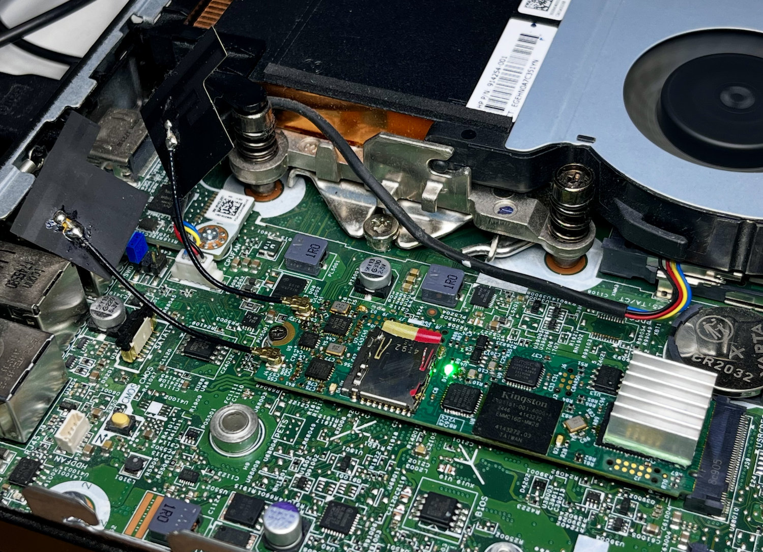
Setting up a smart home hub, such as running Home Assistant, often requires hardware with sufficient performance and connectivity options. Many existing solutions, like Raspberry Pi, may be insufficient for advanced automation tasks due to a low-power CPU or a slow microSD card on which the OS is installed. A good alternative could be an x86 mini PC, but these often lack expansion ports.
M2SmartHome is an add-on card that operates on PCIe 2.0 x1 and can be installed in any M.2 2280 Key M-equipped device. By integrating multiple essential components into a single device, it eliminates the need for external adapters and additional hardware.
The device is equipped with onboard eMMC memory, an SD card reader, WiFi 802.11n 2.4GHz radio (RTL8188), and a Thread radio (EFR32) from Silicon Labs. Once installed in an M.2 slot, it provides both storage for the operating system and enhanced connectivity, making it an ideal choice for smart home setups.
On the diagram below siplified system architecture has been presented. PCIe 2.0 x1 interface from host device is connected to PCIe bridge. To four USB 2.0 ports all crucial components are connected: eMMC memory controller, micro SD card controller, USB to UART bridge with Thread / ZigBee RF SOC and WiFi network card.
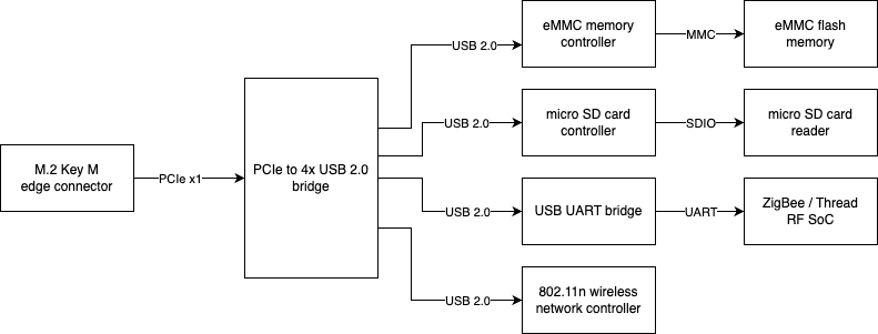
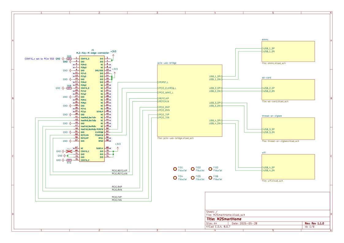
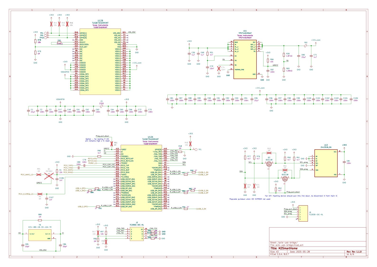
As a PCIe bridge choosen the TUSB7340 manufactured by Texas Instruments. TUSB7340 is a PCIe-to-USB 3.0 host controller with a single line PCIe interface, compliant with the PCIe Specification 2.0, supporting programmable driver current, de-emphasis levels, and advanced power management (L0, L0s, L1, L2, L2/L3Ready, L3, D0, D3Hot, D3Cold). It features four USB 3.0 ports as well as USB 2.0 data lines with EHCI (480 Mbps) and OHCI (12 Mbps, 1.5 Mbps) controllers for high-, full-, and low-speed transactions. An EEPROM connected via I²C has been added to enable optional features and configurable settings. Additionally TagConnect TC2030 6-pin connector has been added for flashing I²C EEPROM and TC2050 10-pin connector for accesing TUSB7340 JTAG.
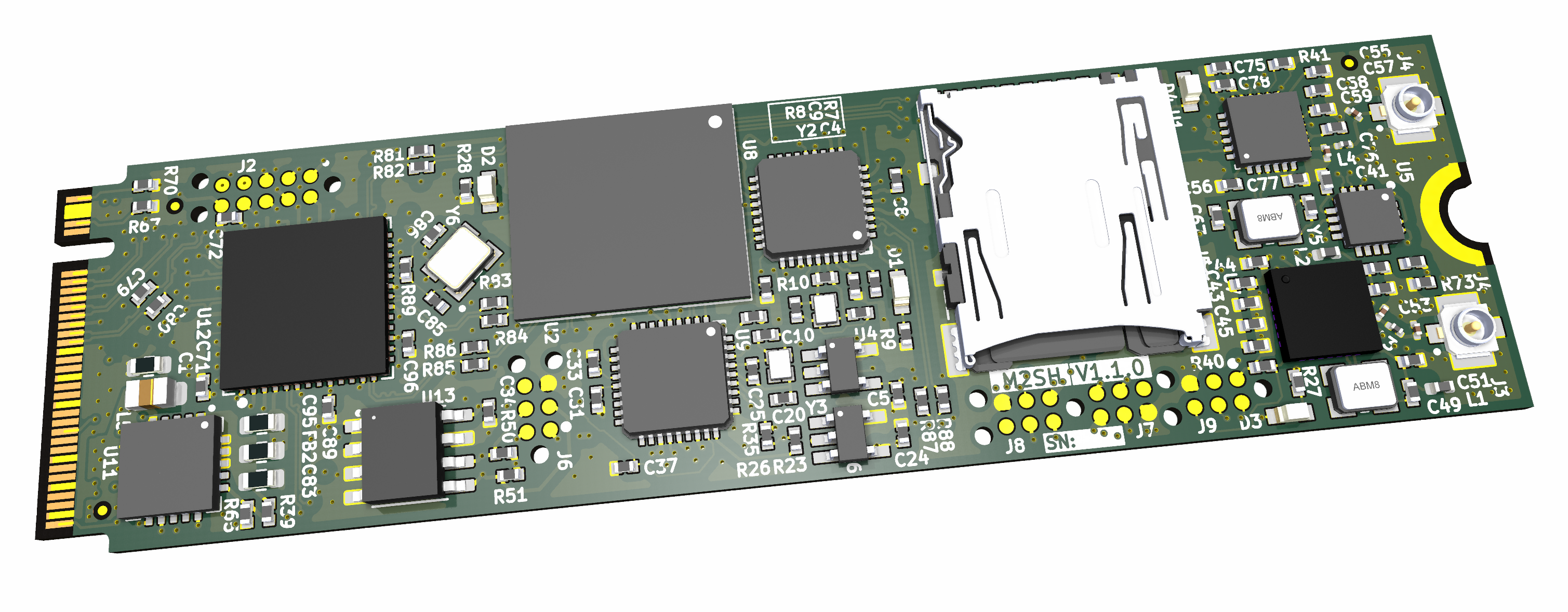
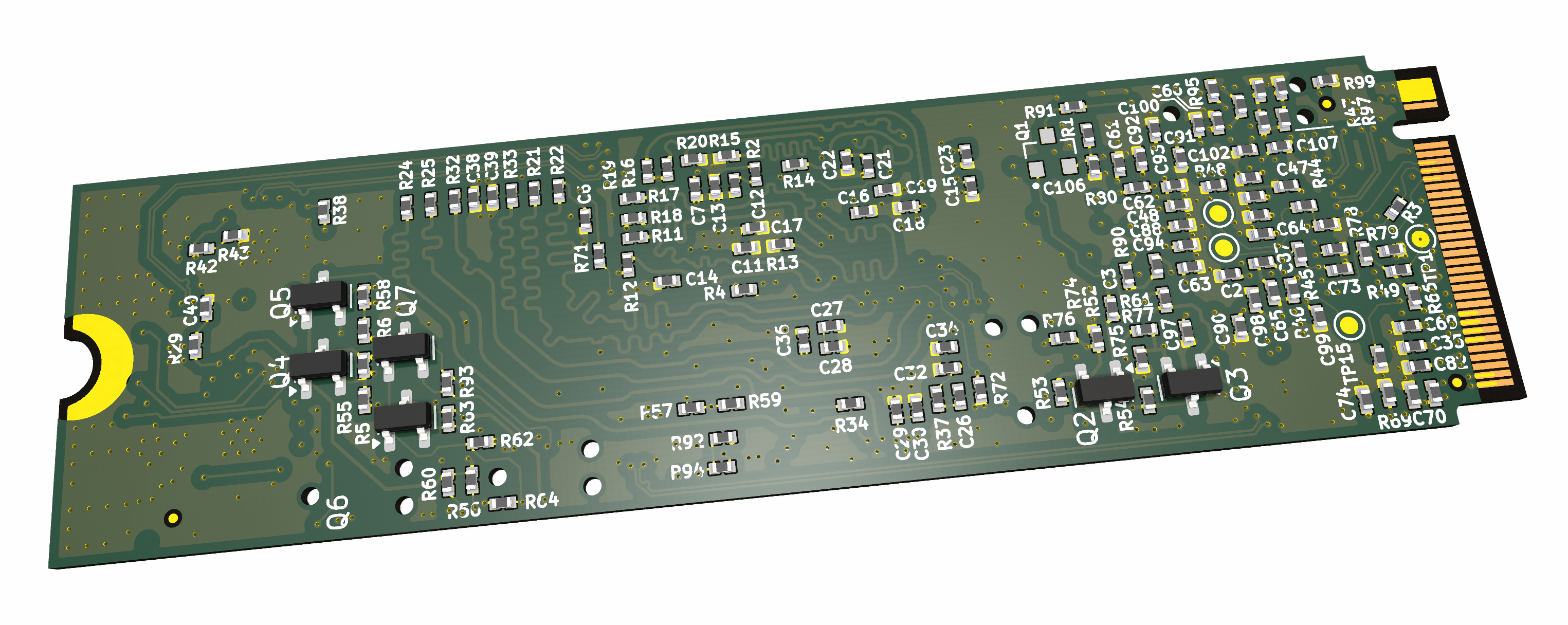
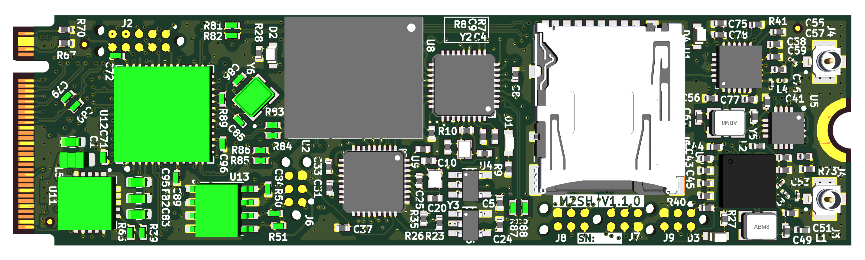
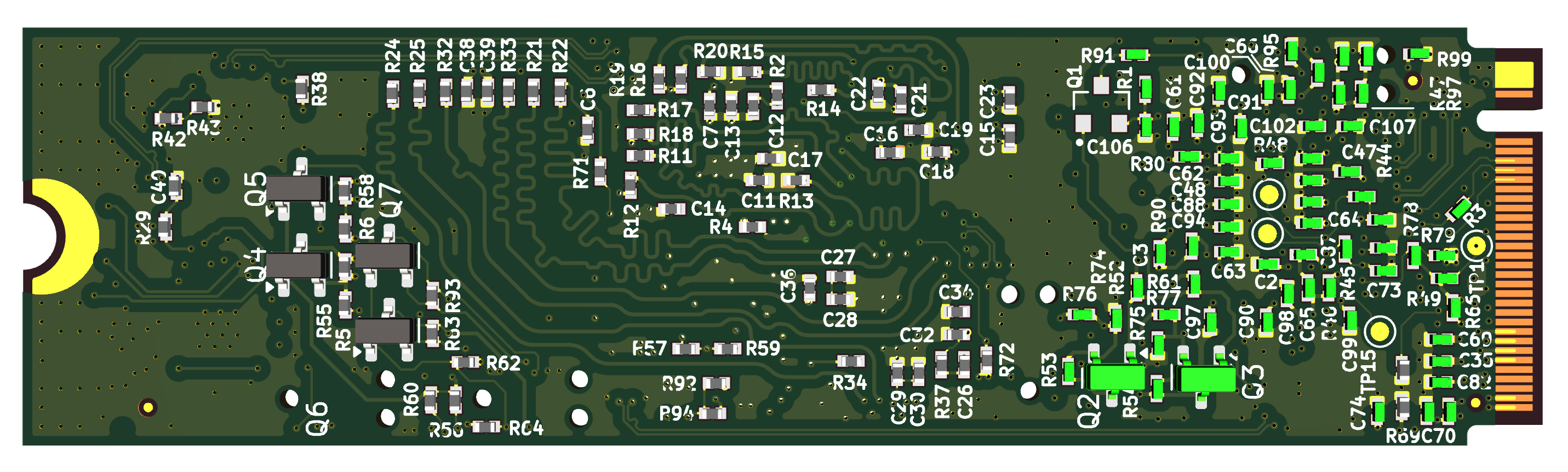
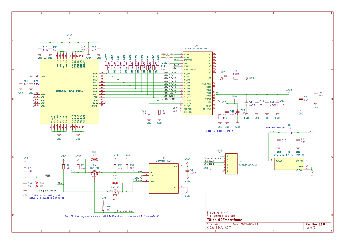
Components related to this part of the schematic has been highlighted in green on the board view:
The USB2244 is connected to a TUSB7340 PCIe-to-USB bridge, acting as a USB 2.0-to-eMMC controller for Kingston’s EMMC16G-MW28-01E10, with a Microchip 24AA04T-I/OT EEPROM for optional configuration. The eMMC is powered directly from the M.2 3.3V rail, eliminating the need for an LDO. The eMMC interface uses D0–D8, CMD, and CLK lines, with 49.9kΩ pull-ups on CMD and data lines. The EEPROM is connected via I²C (SCL, SDA) with 4.7kΩ pull-ups, storing configuration settings for the USB controller. This setup provides high-speed eMMC access over USB in an M.2 form factor.
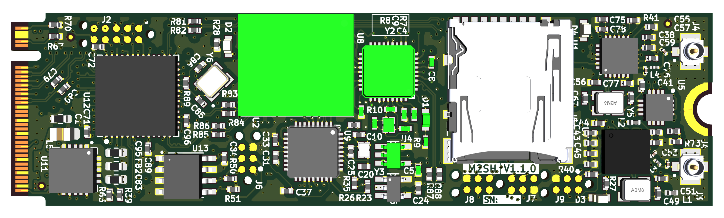
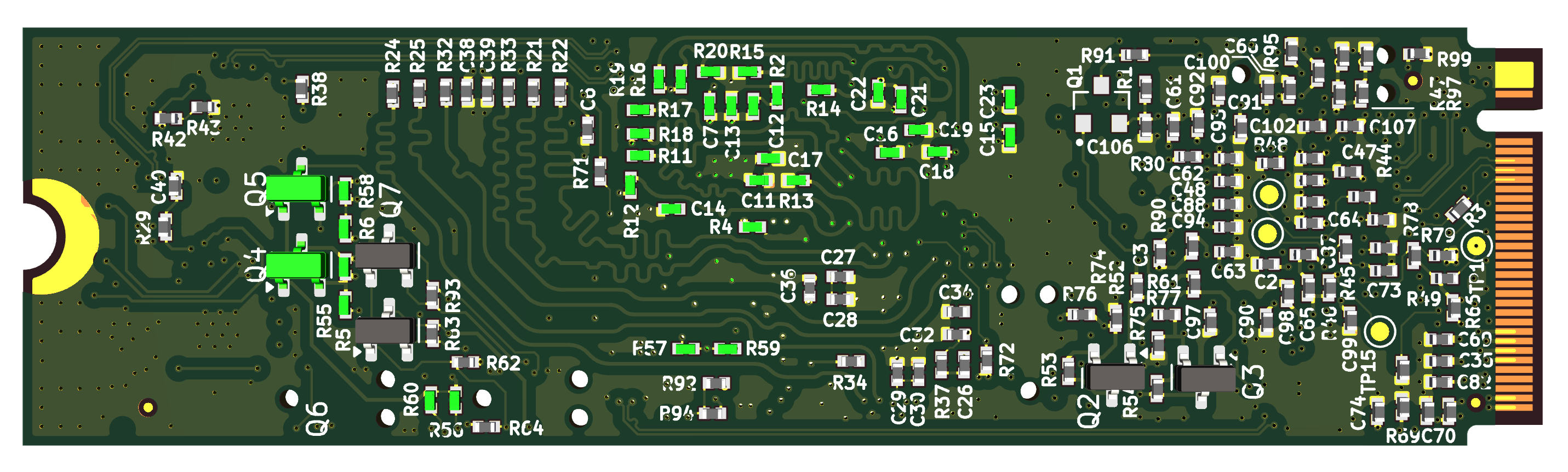
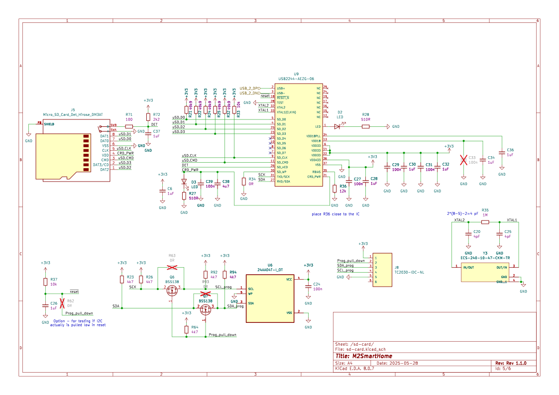
The USB2244 controller interfaces with a Hirose DM3AT-SF-PEJM5 push-push microSD card slot and with a Microchip 24AA04T-I/OT EEPROM for configuration storage. The microSD card is powered by the internal 3.3V regulator of the USB2244. The SD interface utilizes CLK, CMD, and D0–D3 lines, with 49.9kΩ pull-ups on CMD and data lines for stable operation. The EEPROM is connected via I²C (SCL, SDA) with 4.7kΩ pull-ups, allowing the USB2244 to load stored device settings at startup. Additionaly TagConnect TC2030
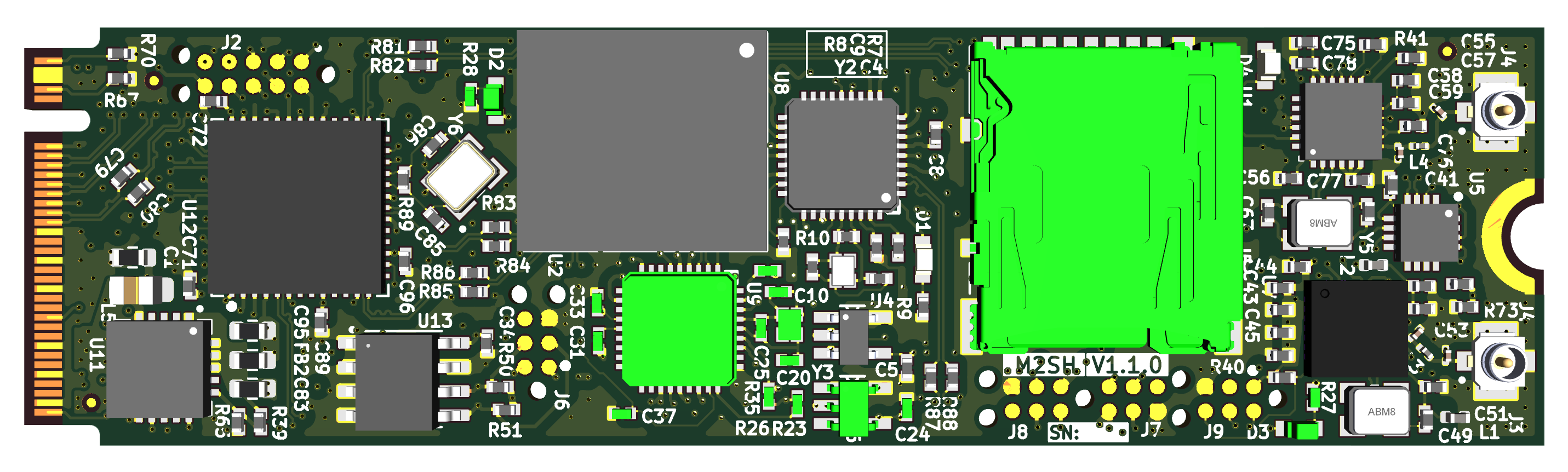
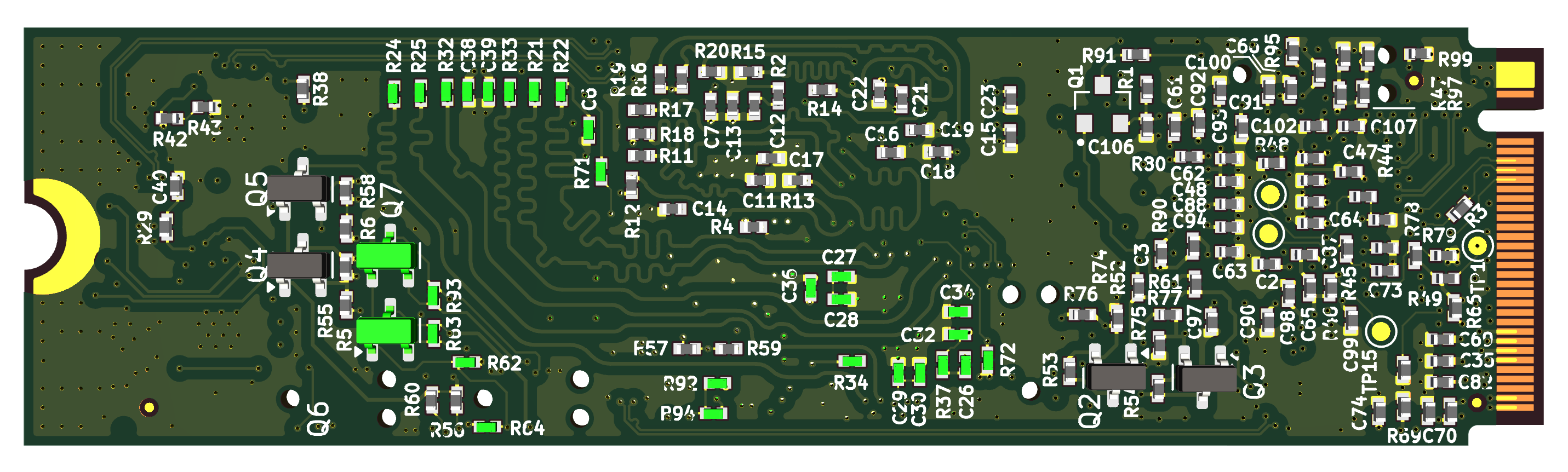
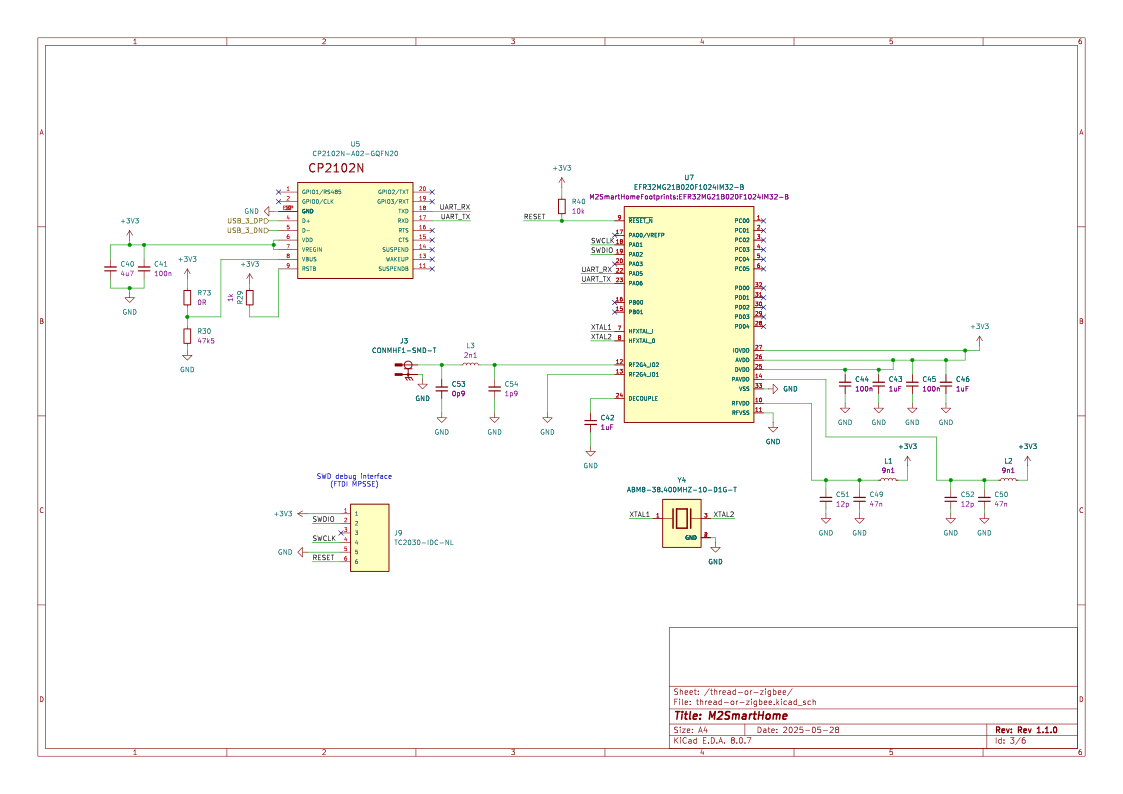
The Silicon Labs EFR32MG21B020F1024IM32-B is a 802.15.4 Thread radio SoC, providing wireless connectivity, while the Silicon Labs CP2102N-A02-GQFN20 acts as a USB-to-UART bridge for communication with a host system. The EFR32MG21 is powered from the M.2 3.3V rail, with its radio interface using an external antenna for Thread communication. The CP2102N is connected via USB 2.0 (D+, D-) to the host via PCIe USB bridge.
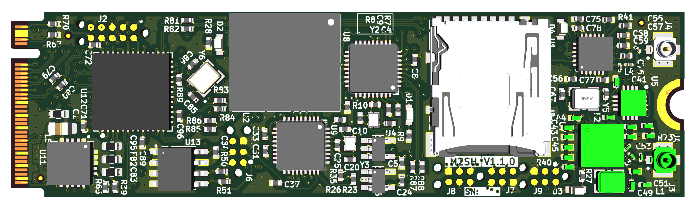
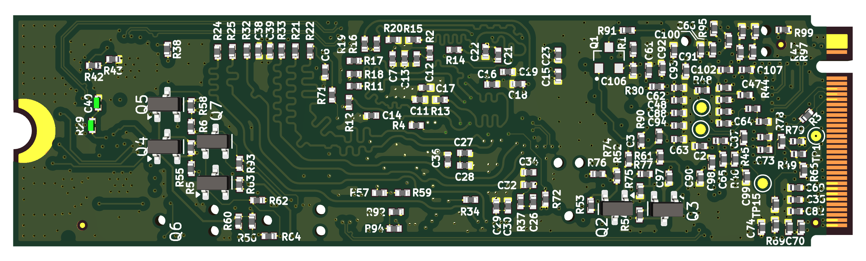
The Realtek RTL8188FTV-VC-CG is a WiFi 802.11b/g/n 2.4GHz radio SoC, providing wireless connectivity. It is powered from the M.2 3.3V rail and interfaces with the host system via a USB 2.0 connection. The RF section is connected to an external antenna.
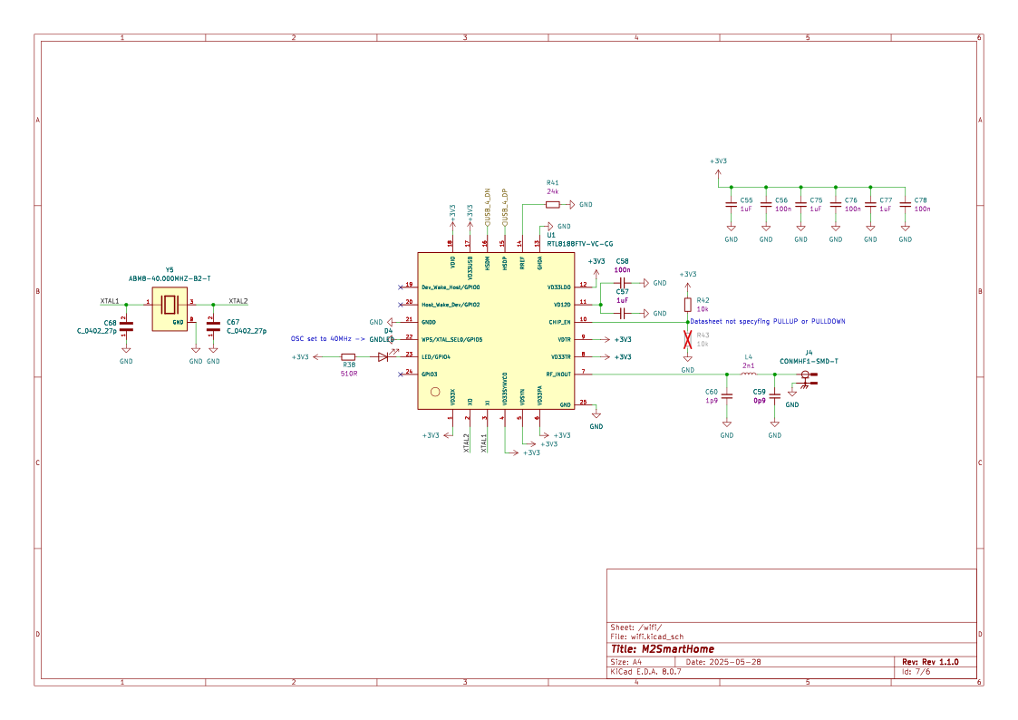
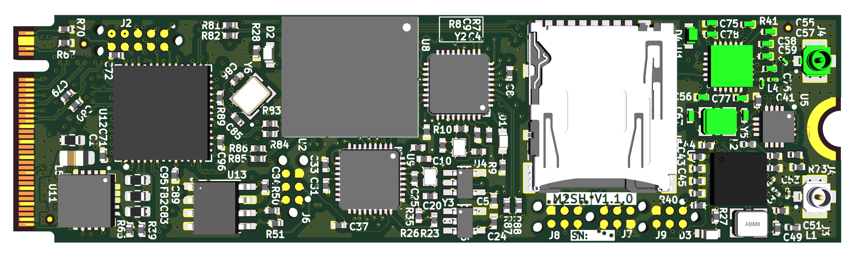
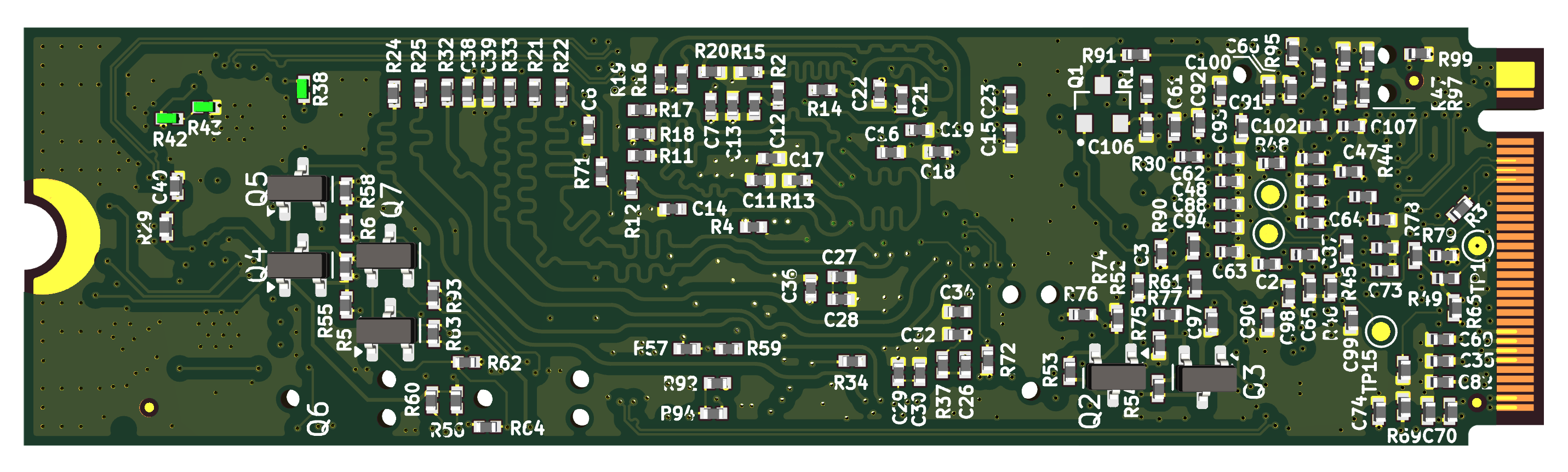
The PCB was manufactured by JLCPCB, using Gerber files generated by the CI job kicad_release_CI.yml. The board features a 6-layer design with the standard stack-up JLC06081H-2116.
While the board includes a few high-speed signals, such as USB 2.0 and PCIe 2.0, these interfaces are relatively tolerant of signal integrity variations. As a result, impedance maps were not created for this design.
All PCB order settings are detailed below.
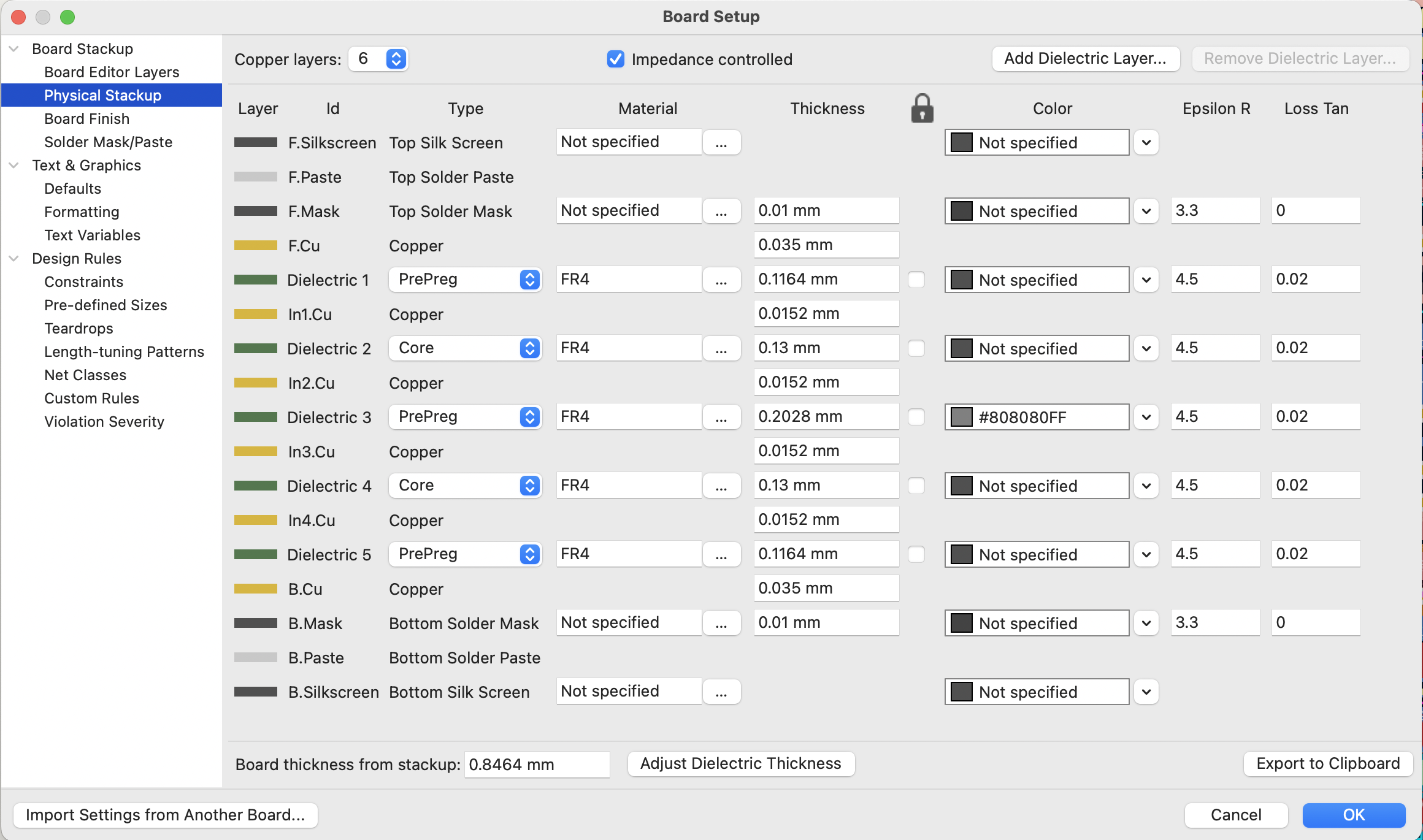
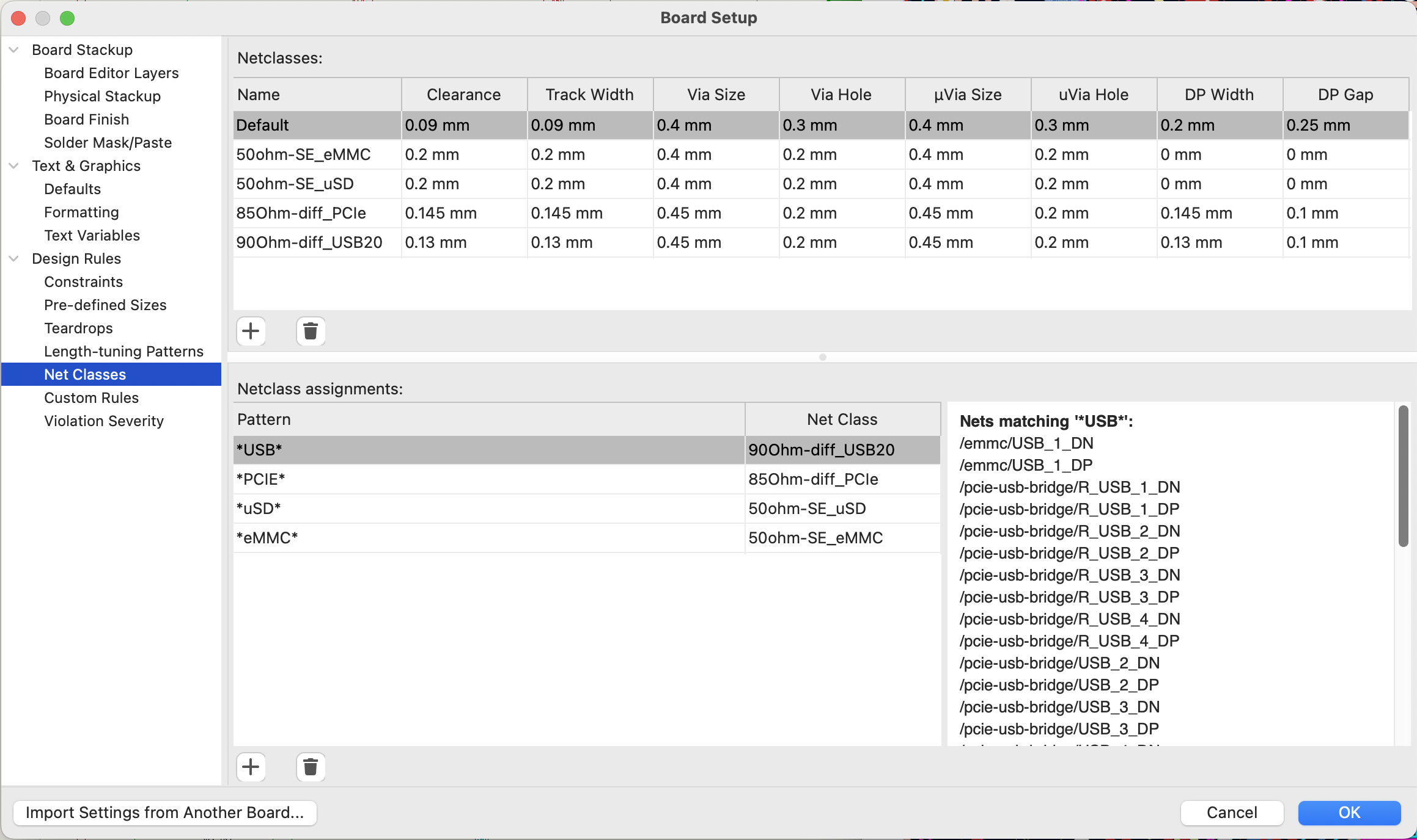
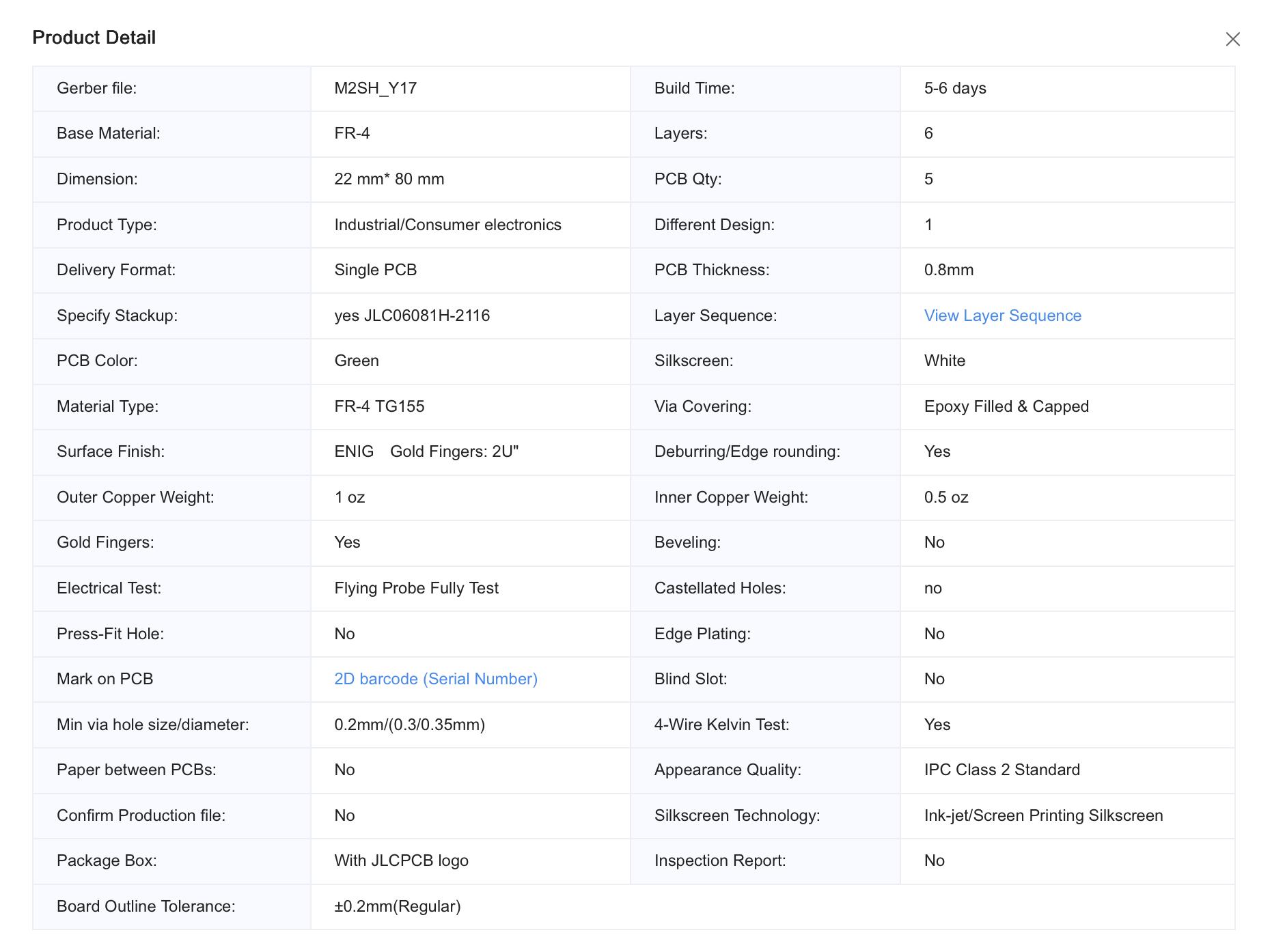
Components were sourced via the Octopart API, with OEMSecrets used to optimize the Bill of Materials (BOM) cost. For assembly, SN42Bi58 low-temperature solder paste was applied, and all components were manually placed using tweezers.
The top side of the board was soldered using a UYUE 946C hotplate, with a preheat stage of 1 minute at 100 °C followed by a 2-minute reflow up to 330 °C. The bottom side was soldered using a preheater set to 100 °C and a hot air gun set to 360 °C.
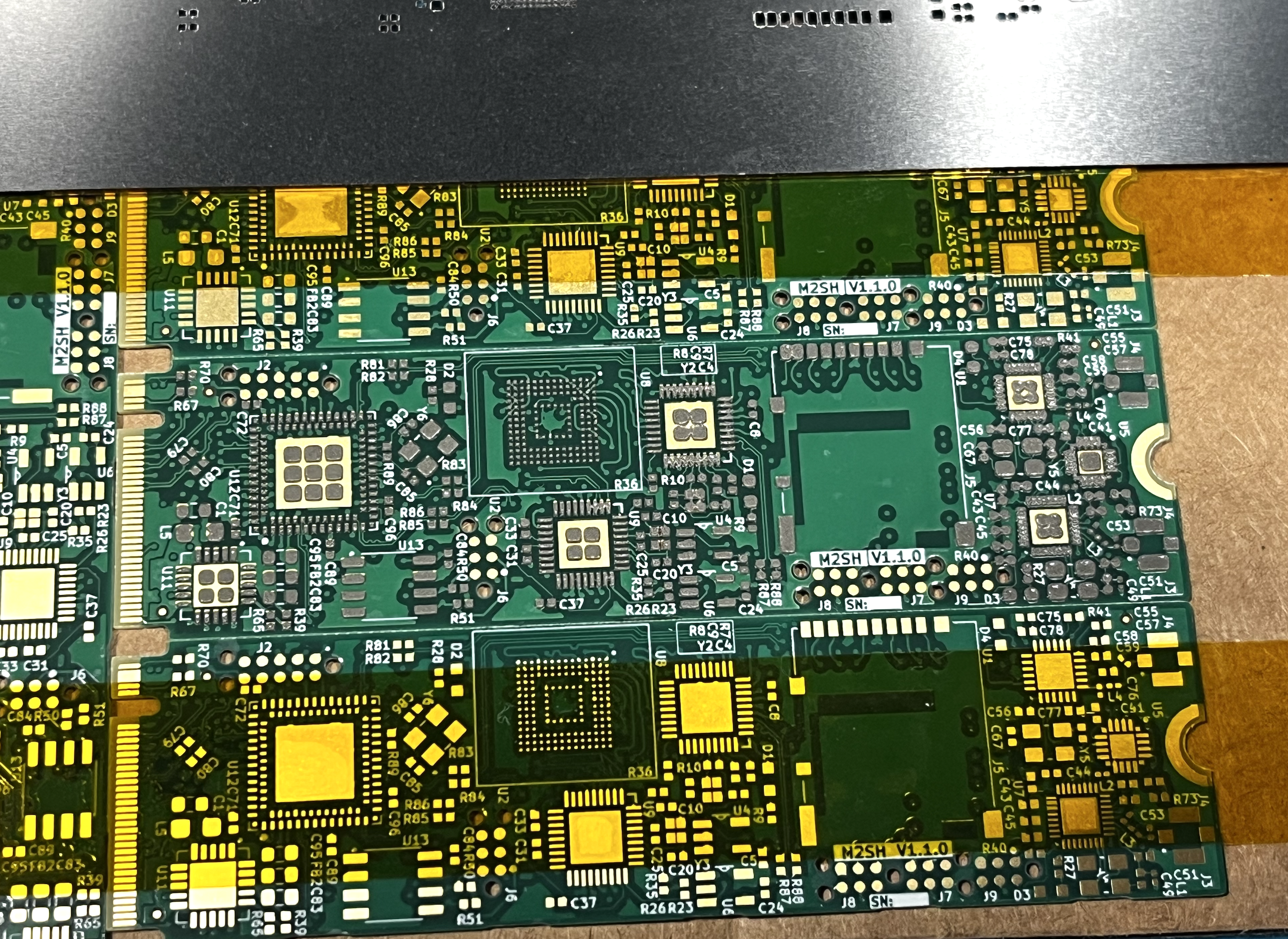
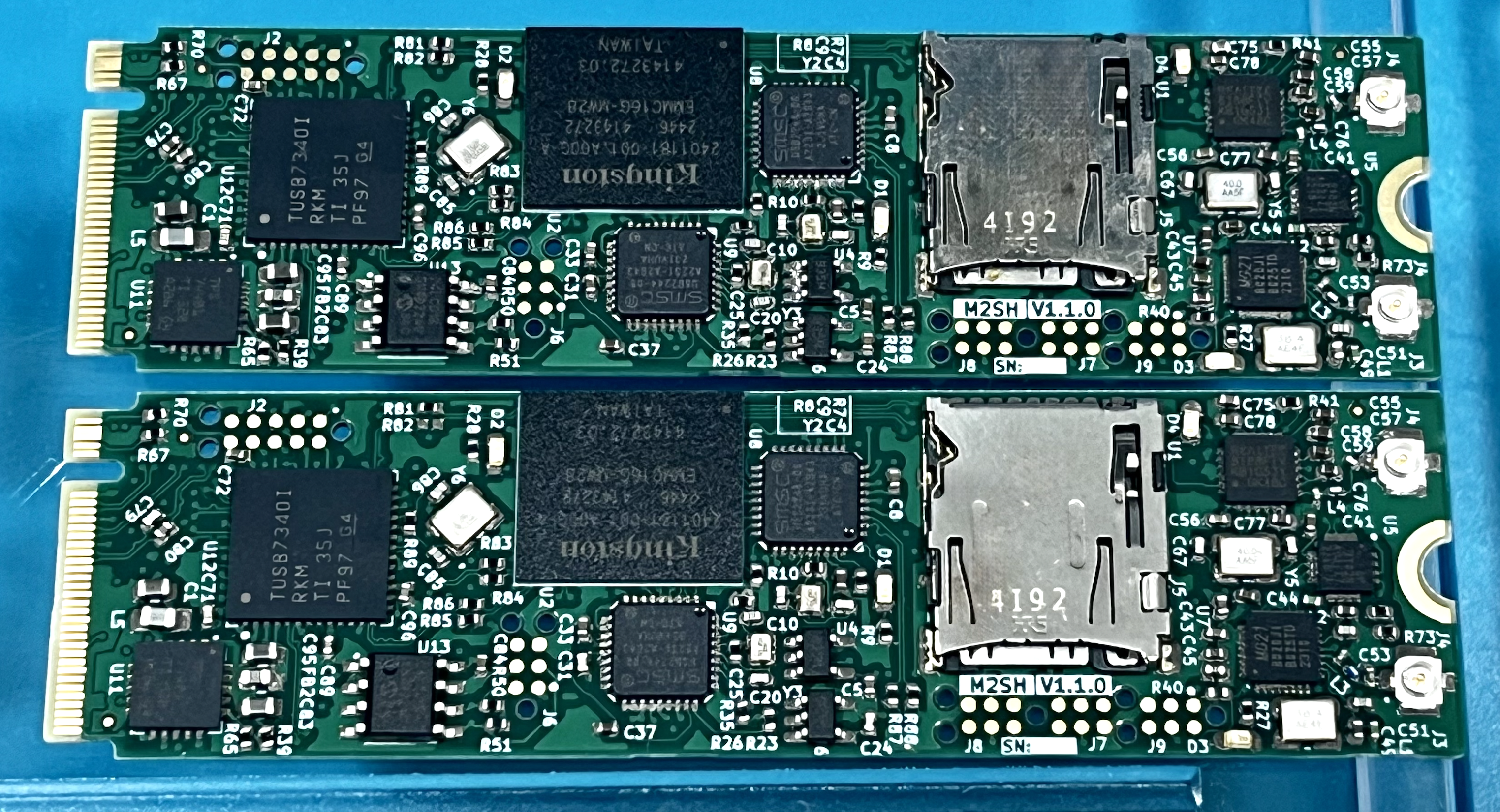
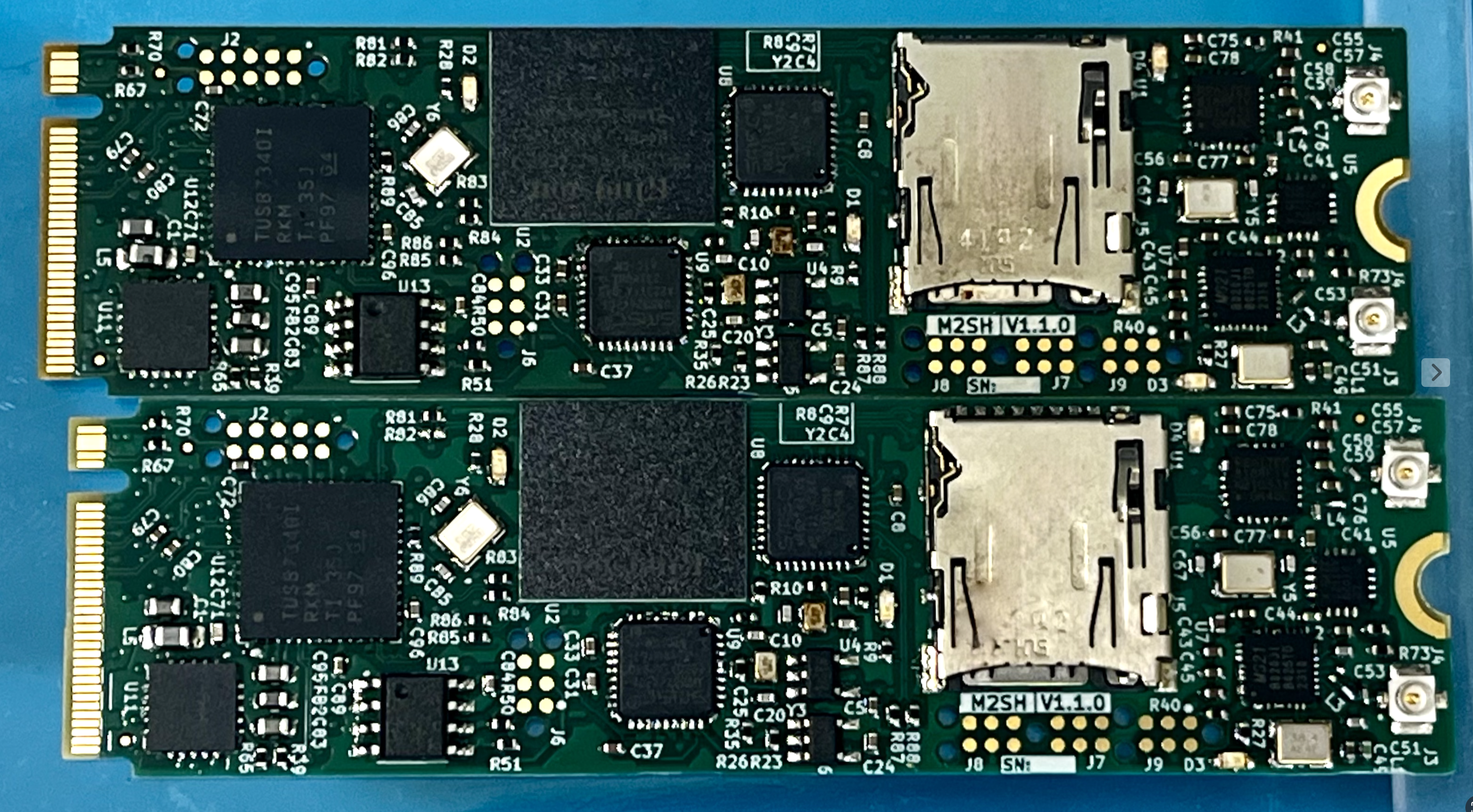
Rev.1.1.0 is not flawless, a few moodifications are required
Board bringup starts with visual inspecion, completion check, as well as DNP components check. Removed all shorts and corrected invidual components using soldering iron.
First powering up - using lab bench power supply connected to +3V3 power bus, with current limit set to 400 mA.
All tests were performed using x86 architecture 64 bit computer. In this case HP EliteDesk 800 G3 USFF. All tests performed using Ubuntu 24.04 LTS. For testing thread and wifi used LXC LXC1BL4820240722009 2.4 GHz tuned antennas.
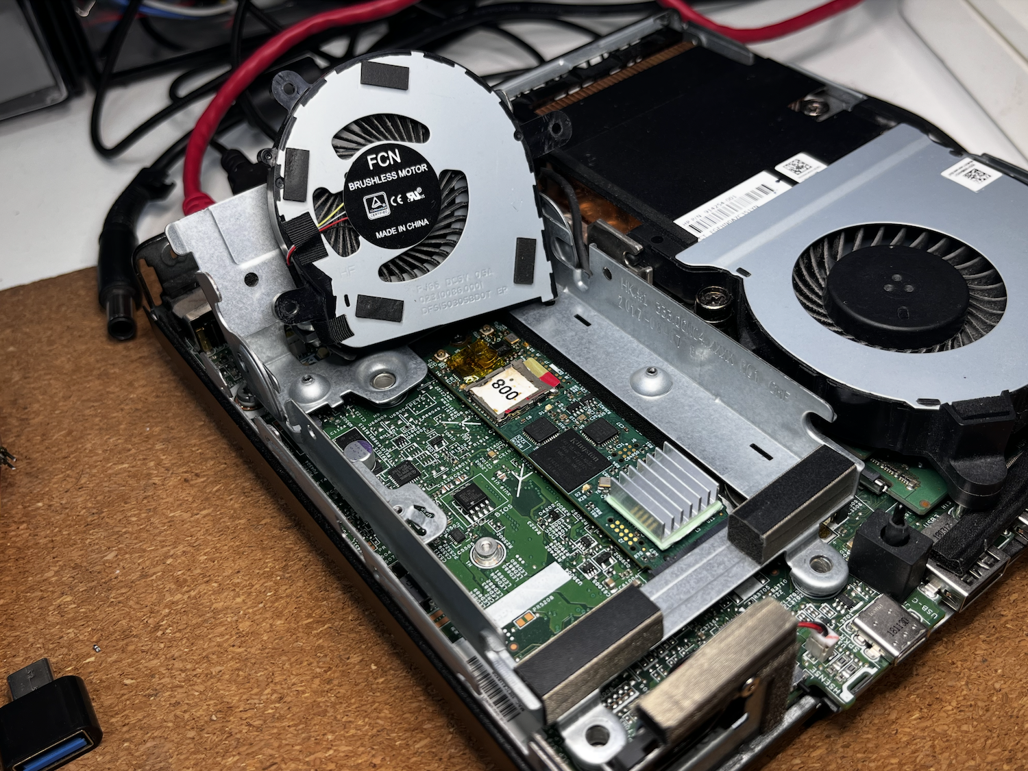
After turning on PC, after operating system loads, when prompted in terminal sudo lspci -vvv | grep -A 80 TUSB, verbose output of the lspci should looks like below. If so PCIe bridge is working and properly detected by the host.
01:00.0 USB controller: Texas Instruments TUSB73x0 SuperSpeed USB 3.0 xHCI Host Controller (rev 02) (prog-if 30 [XHCI])
        Control: I/O- Mem+ BusMaster+ SpecCycle- MemWINV- VGASnoop- ParErr- Stepping- SERR+ FastB2B- DisINTx+
        Status: Cap+ 66MHz- UDF- FastB2B- ParErr- DEVSEL=fast >TAbort- <TAbort- <MAbort- >SERR- <PERR- INTx-
        Latency: 0, Cache Line Size: 64 bytes
        Interrupt: pin A routed to IRQ 16
        Region 0: Memory at ce900000 (64-bit, non-prefetchable) [size=64K]
        Region 2: Memory at ce910000 (64-bit, non-prefetchable) [size=8K]
        Capabilities: [40] Power Management version 3
                Flags: PMEClk- DSI- D1+ D2+ AuxCurrent=0mA PME(D0+,D1+,D2+,D3hot+,D3cold-)
                Status: D0 NoSoftRst+ PME-Enable- DSel=0 DScale=0 PME-
        Capabilities: [48] MSI: Enable- Count=1/8 Maskable- 64bit+
                Address: 0000000000000000  Data: 0000
        Capabilities: [70] Express (v2) Endpoint, MSI 00
                DevCap: MaxPayload 1024 bytes, PhantFunc 0, Latency L0s unlimited, L1 unlimited
                        ExtTag- AttnBtn- AttnInd- PwrInd- RBE+ FLReset- SlotPowerLimit 25W
                DevCtl: CorrErr+ NonFatalErr+ FatalErr+ UnsupReq+
                        RlxdOrd+ ExtTag- PhantFunc- AuxPwr- NoSnoop-
                        MaxPayload 256 bytes, MaxReadReq 512 bytes
                DevSta: CorrErr- NonFatalErr- FatalErr- UnsupReq- AuxPwr- TransPend-
                LnkCap: Port #0, Speed 5GT/s, Width x1, ASPM L0s L1, Exit Latency L0s <512ns, L1 <64us
                        ClockPM+ Surprise- LLActRep- BwNot- ASPMOptComp-
                LnkCtl: ASPM L0s L1 Enabled; RCB 64 bytes, Disabled- CommClk+
                        ExtSynch- ClockPM+ AutWidDis- BWInt- AutBWInt-
LnkSta: Speed 5GT/s, Width x1Additionally also USB HUB should be visible. When prompted sudo lsusb -vvv | grep -A 80 TUSB operating system should return similar config to seen below.
01:00.0 USB controller [0c03]: Texas Instruments TUSB73x0 SuperSpeed USB 3.0 xHCI Host Controller [104c:8241] (rev 02) (prog-if 30 [XHCI])
	Control: I/O- Mem+ BusMaster+ SpecCycle- MemWINV- VGASnoop- ParErr- Stepping- SERR+ FastB2B- DisINTx+
	Status: Cap+ 66MHz- UDF- FastB2B- ParErr- DEVSEL=fast >TAbort- <TAbort- <MAbort- >SERR- <PERR- INTx-
	Latency: 0, Cache Line Size: 64 bytes
	Interrupt: pin A routed to IRQ 16
	Region 0: Memory at ce900000 (64-bit, non-prefetchable) [size=64K]
	Region 2: Memory at ce910000 (64-bit, non-prefetchable) [size=8K]
	Capabilities: [40] Power Management version 3
		Flags: PMEClk- DSI- D1+ D2+ AuxCurrent=0mA PME(D0+,D1+,D2+,D3hot+,D3cold-)
		Status: D0 NoSoftRst+ PME-Enable- DSel=0 DScale=0 PME-
	Capabilities: [48] MSI: Enable- Count=1/8 Maskable- 64bit+
		Address: 0000000000000000  Data: 0000
	Capabilities: [70] Express (v2) Endpoint, MSI 00
		DevCap:	MaxPayload 1024 bytes, PhantFunc 0, Latency L0s unlimited, L1 unlimited
			ExtTag- AttnBtn- AttnInd- PwrInd- RBE+ FLReset- SlotPowerLimit 25W
		DevCtl:	CorrErr+ NonFatalErr+ FatalErr+ UnsupReq+
			RlxdOrd+ ExtTag- PhantFunc- AuxPwr- NoSnoop-
			MaxPayload 256 bytes, MaxReadReq 512 bytes
		DevSta:	CorrErr- NonFatalErr- FatalErr- UnsupReq- AuxPwr- TransPend-
		LnkCap:	Port #0, Speed 5GT/s, Width x1, ASPM L0s L1, Exit Latency L0s <512ns, L1 <64us
			ClockPM+ Surprise- LLActRep- BwNot- ASPMOptComp-
		LnkCtl:	ASPM L0s L1 Enabled; RCB 64 bytes, Disabled- CommClk+
			ExtSynch- ClockPM+ AutWidDis- BWInt- AutBWInt-
LnkSta: Speed 5GT/s, Width x1Additionally may read PCIe config in pure hex form (sudo lspci -s 01:00 -xxx) which can be usefull for customization of the controller setting as it directly reflects memory adresses in I2C EEPROM connected to it.
01:00.0 USB controller: Texas Instruments TUSB73x0 SuperSpeed USB 3.0 xHCI Host Controller (rev 02)
00: 4c 10 41 82 06 05 10 00 02 30 03 0c 10 00 00 00
10: 04 00 90 ce 00 00 00 00 04 00 91 ce 00 00 00 00
20: 00 00 00 00 00 00 00 00 00 00 00 00 00 00 00 00
30: 00 00 00 00 40 00 00 00 00 00 00 00 ff 01 00 00
40: 01 48 03 7e 08 00 00 00 05 70 86 00 00 00 00 00
50: 00 00 00 00 00 00 00 00 00 00 00 00 00 00 00 00
60: 30 20 00 00 00 00 00 00 00 00 00 00 00 00 00 00
70: 10 c0 02 00 c3 8f e8 07 3f 20 00 00 12 3c 07 00
80: 43 01 12 10 00 00 00 00 00 00 00 00 00 00 00 00
90: 00 00 00 00 10 00 00 00 00 00 00 00 00 00 00 00
a0: 02 00 00 00 00 00 00 00 00 00 00 00 00 00 00 00
b0: 00 00 00 00 00 00 0f 00 00 00 00 00 00 00 00 00
c0: 11 00 07 80 02 00 00 00 02 10 00 00 00 00 00 00
d0: 00 00 00 00 ab 0d 00 00 1b 00 00 00 3f 00 00 00
e0: 00 00 00 00 00 00 00 00 00 00 00 00 00 00 00 00
f0: 00 00 00 00 00 00 00 00 00 00 00 00 00 00 00 00
Last check is in a tree form if all four USB devices connected to the hub are visible (sudo lsusb -vt).
/:  Bus 003.Port 001: Dev 001, Class=root_hub, Driver=xhci_hcd/4p, 480M
    ID 1d6b:0002 Linux Foundation 2.0 root hub
    |__ Port 001: Dev 002, If 0, Class=Vendor Specific Class, Driver=rtl8xxxu, 480M
        ID 0bda:f179 Realtek Semiconductor Corp. RTL8188FTV 802.11b/g/n 1T1R 2.4G WLAN Adapter
    |__ Port 002: Dev 003, If 0, Class=Mass Storage, Driver=usb-storage, 480M
        ID 0424:2240 Microchip Technology, Inc. (formerly SMSC)
    |__ Port 003: Dev 004, If 0, Class=Vendor Specific Class, Driver=cp210x, 12M
        ID 10c4:ea60 Silicon Labs CP210x UART Bridge
    |__ Port 004: Dev 005, If 0, Class=Mass Storage, Driver=usb-storage, 480M
        ID 0424:2240 Microchip Technology, Inc. (formerly SMSC)
eMMC controller is connected to fourth port of USB HUB present in PCIe bridge (sudo lsusb -vt). Note that exact same chip is used for micro SD card slot, but connected to two.
/:  Bus 003.Port 001: Dev 001, Class=root_hub, Driver=xhci_hcd/4p, 480M
    ID 1d6b:0002 Linux Foundation 2.0 root hub
    |__ Port 001: Dev 002, If 0, Class=Vendor Specific Class, Driver=rtl8xxxu, 480M
        ID 0bda:f179 Realtek Semiconductor Corp. RTL8188FTV 802.11b/g/n 1T1R 2.4G WLAN Adapter
    |__ Port 002: Dev 003, If 0, Class=Mass Storage, Driver=usb-storage, 480M
        ID 0424:2240 Microchip Technology, Inc. (formerly SMSC)
    |__ Port 003: Dev 004, If 0, Class=Vendor Specific Class, Driver=cp210x, 12M
        ID 10c4:ea60 Silicon Labs CP210x UART Bridge
    |__ Port 004: Dev 005, If 0, Class=Mass Storage, Driver=usb-storage, 480M
        ID 0424:2240 Microchip Technology, Inc. (formerly SMSC) <---------------------------
It's configuration can be read using lsusb -d 0424:2240 -vvv and should be similar to the one below.
Bus 001 Device 008: ID 0424:2240 Microchip Technology, Inc. (formerly SMSC) Ultra Fast Media
Couldn't open device, some information will be missing
Device Descriptor:
bLength 18
bDescriptorType 1
bcdUSB 2.00
bDeviceClass 0 [unknown]
bDeviceSubClass 0 [unknown]
bDeviceProtocol 0
bMaxPacketSize0 64
idVendor 0x0424 Microchip Technology, Inc. (formerly SMSC)
idProduct 0x2240 Ultra Fast Media
bcdDevice 1.98
iManufacturer 1 Generic
iProduct 2 Ultra Fast Media
iSerial 3 000000225001
bNumConfigurations 1
Configuration Descriptor:
bLength 9
bDescriptorType 2
wTotalLength 0x0020
bNumInterfaces 1
bConfigurationValue 1
iConfiguration 0If eMMC memory connected to controller is seen properly it should be listed as block device lsblk with correct memory - something below 16GB.
NAME MAJ:MIN RM SIZE RO TYPE MOUNTPOINTS
sdb 8:16 1 14.6G 0 disk
Additionally, it's recommended to check kernel debug messages during system startup to ensure no errors were reported. This can be done using the command: sudo dmesg.
[ 2402.769465] usb 1-13: new high-speed USB device number 8 using xhci_hcd
[ 2402.902304] usb 1-13: New USB device found, idVendor=0424, idProduct=2240, bcdDevice= 1.98
[ 2402.902327] usb 1-13: New USB device strings: Mfr=1, Product=2, SerialNumber=3
[ 2402.902335] usb 1-13: Product: Ultra Fast Media
[ 2402.902341] usb 1-13: Manufacturer: Generic
[ 2402.902347] usb 1-13: SerialNumber: 000000225001
[ 2402.907570] usb-storage 1-13:1.0: USB Mass Storage device detected
[ 2402.907866] scsi host2: usb-storage 1-13:1.0
[ 2403.963071] scsi 2:0:0:0: Direct-Access Generic Ultra HS-COMBO 1.98 PQ: 0 ANSI: 0
[ 2403.963267] sd 2:0:0:0: Attached scsi generic sg1 type 0
[ 2403.969432] sd 2:0:0:0: [sdb] 30615552 512-byte logical blocks: (15.7 GB/14.6 GiB)
[ 2403.970000] sd 2:0:0:0: [sdb] Write Protect is off
[ 2403.970004] sd 2:0:0:0: [sdb] Mode Sense: 23 00 00 00
[ 2403.970608] sd 2:0:0:0: [sdb] No Caching mode page found
[ 2403.970611] sd 2:0:0:0: [sdb] Assuming drive cache: write through
[ 2403.974170] sd 2:0:0:0: [sdb] Attached SCSI removable disk
It is recommended to quickly benchmark the memory using Gnome Disks tool, as inproperly solder may result in lower read/write speeds. The expected average read speed around 33MB/s and average access time below 1 ms.
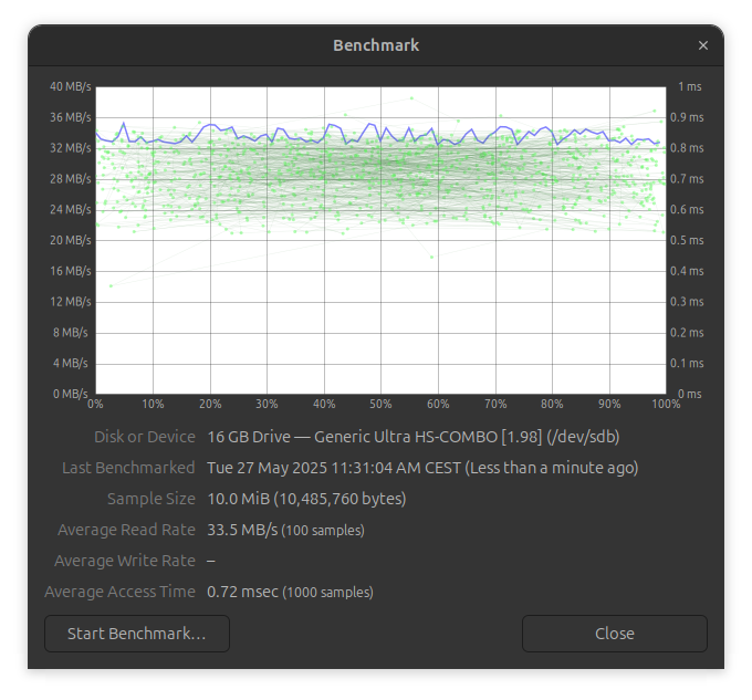
For more detailed benchmark used KDiskMark, which have option to select test file size and generate different write/read patterns beeing closer to more real life scenario.
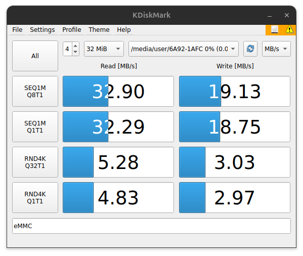
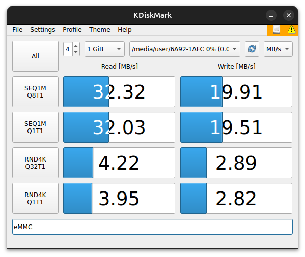
For complete test may use badblocks as a extended write/read test which took aproximately 6 hours. Application writes patterns to the entire memory surface and checks if all data has been written correctly. Usage sudo badblocks -wsv /dev/sdX
Checking for bad blocks in read-write mode
From block 0 to 15307775
Testing with pattern 0xaa: done
Reading and comparing: done
Testing with pattern 0x55: done
Reading and comparing: done
Testing with pattern 0xff: done
Reading and comparing: done
Testing with pattern 0x00: done
Reading and comparing: done
Pass completed, 0 bad blocks found. (0/0/0 errors)
uSD controller is connected to second port of USB HUB present in PCIe bridge (sudo lsusb -vt).
/:  Bus 003.Port 001: Dev 001, Class=root_hub, Driver=xhci_hcd/4p, 480M
    ID 1d6b:0002 Linux Foundation 2.0 root hub
    |__ Port 001: Dev 002, If 0, Class=Vendor Specific Class, Driver=rtl8xxxu, 480M
        ID 0bda:f179 Realtek Semiconductor Corp. RTL8188FTV 802.11b/g/n 1T1R 2.4G WLAN Adapter
    |__ Port 002: Dev 003, If 0, Class=Mass Storage, Driver=usb-storage, 480M
        ID 0424:2240 Microchip Technology, Inc. (formerly SMSC) <---------------------------
    |__ Port 003: Dev 004, If 0, Class=Vendor Specific Class, Driver=cp210x, 12M
        ID 10c4:ea60 Silicon Labs CP210x UART Bridge
    |__ Port 004: Dev 005, If 0, Class=Mass Storage, Driver=usb-storage, 480M
        ID 0424:2240 Microchip Technology, Inc. (formerly SMSC)
It's configuration can be read using lsusb -d 0424:2240 -vvv and should be similar to the one below.
Bus 003 Device 003: ID 0424:2240 Microchip Technology, Inc. (formerly SMSC) Ultra Fast Media
Couldn't open device, some information will be missing
Device Descriptor:
bLength 18
bDescriptorType 1
bcdUSB 2.00
bDeviceClass 0 [unknown]
bDeviceSubClass 0 [unknown]
bDeviceProtocol 0
bMaxPacketSize0 64
idVendor 0x0424 Microchip Technology, Inc. (formerly SMSC)
idProduct 0x2240 Ultra Fast Media
bcdDevice 1.98
iManufacturer 1 Generic
iProduct 2 Ultra Fast Media
iSerial 3 000000225001
bNumConfigurations 1
Configuration Descriptor:
bLength 9
bDescriptorType 2
wTotalLength 0x0020
bNumInterfaces 1
bConfigurationValue 1
iConfiguration 0Insert micro SD card into slot (it is hot pluggable, may be connected when powered on). If uSD memory connected to controller is seen properly it should be listed as block device lsblk with correct memory - corresponding to the size of inserted card.
NAME MAJ:MIN RM SIZE RO TYPE MOUNTPOINTS
sdb 8:16 1 3.7G 0 disk
└─sdb1 8:17 1 3.7G 0 part /media/user/9016-4EF8
Additionally, it's recommended to check kernel debug messages during system startup to ensure no errors were reported. This can be done using the command: sudo dmesg. Messages with connected just empty reader:
[ 33.892694] usb 1-13: new high-speed USB device number 5 using xhci_hcd
[ 34.027971] usb 1-13: New USB device found, idVendor=0424, idProduct=2240, bcdDevice= 1.98
[ 34.027977] usb 1-13: New USB device strings: Mfr=1, Product=2, SerialNumber=3
[ 34.027979] usb 1-13: Product: Ultra Fast Media
[ 34.027981] usb 1-13: Manufacturer: Generic
[ 34.027983] usb 1-13: SerialNumber: 000000225001
[ 34.051629] usb-storage 1-13:1.0: USB Mass Storage device detected
[ 34.051918] scsi host2: usb-storage 1-13:1.0
[ 34.052013] usbcore: registered new interface driver usb-storage
[ 34.054051] usbcore: registered new interface driver uas
[ 35.074189] scsi 2:0:0:0: Direct-Access Generic Ultra HS-COMBO 1.98 PQ: 0 ANSI: 0
[ 35.074516] sd 2:0:0:0: Attached scsi generic sg1 type 0
[ 35.075325] sd 2:0:0:0: [sdb] Media removed, stopped polling
[ 35.075721] sd 2:0:0:0: [sdb] Attached SCSI removable disk
dmesg when inserted 4GB micro SD card:
[ 651.529877] sd 2:0:0:0: [sdb] 7759872 512-byte logical blocks: (3.97 GB/3.70 GiB)
[ 651.531210] sdb: detected capacity change from 0 to 7759872
[ 651.532979] sdb: sdb1
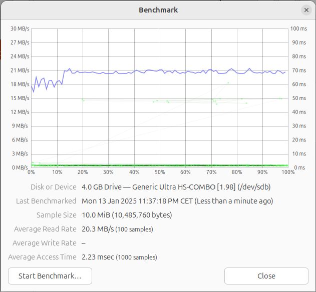
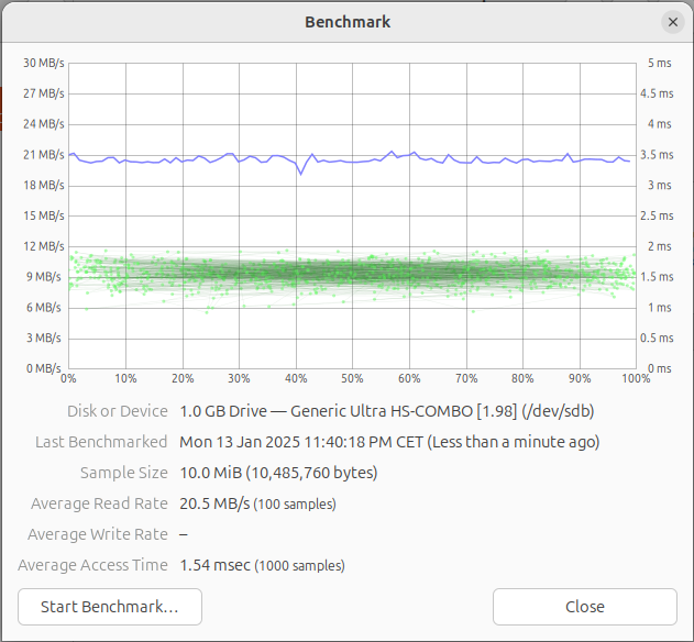
Benchmarked using Gnome Disks tool. Tested 3 different uSD cards.
Off brand 4GB class 4 micro SD card
ATP 1GB SLC industrial micro SD card:
San Disk Extreme 32GB class Ultra 3:
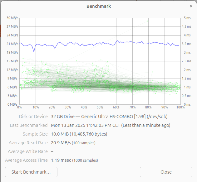
For more detailed benchmark used KDiskMark, which have option to select test file size and generate different write/read patterns beeing closer to more real life scenario.
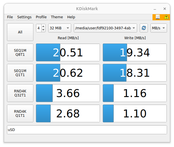
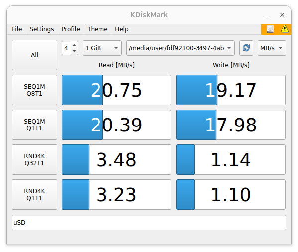
For complete stability test may use badblocks as a extended write/read test which took aproximately 6 hours. Application writes patterns to the entire memory surface and checks if all data has been written correctly. Usage sudo badblocks -wsv /dev/sdX
Checking for bad blocks in read-write mode
From block 0 to 31154687
Testing with pattern 0xaa: done
Reading and comparing: done
Testing with pattern 0x55: done
Reading and comparing: done
Testing with pattern 0xff: done
Reading and comparing: done
Testing with pattern 0x00: done
Reading and comparing: done
Pass completed, 0 bad blocks found. (0/0/0 errors)
Thread radio consist of two main parts USB UART converter and Thread Radio chip.
USB UART controller is connected to the third port of USB HUB present in PCIe bridge (sudo lsusb -vt).
/:  Bus 003.Port 001: Dev 001, Class=root_hub, Driver=xhci_hcd/4p, 480M
    ID 1d6b:0002 Linux Foundation 2.0 root hub
    |__ Port 001: Dev 002, If 0, Class=Vendor Specific Class, Driver=rtl8xxxu, 480M
        ID 0bda:f179 Realtek Semiconductor Corp. RTL8188FTV 802.11b/g/n 1T1R 2.4G WLAN Adapter
    |__ Port 002: Dev 003, If 0, Class=Mass Storage, Driver=usb-storage, 480M
        ID 0424:2240 Microchip Technology, Inc. (formerly SMSC)
    |__ Port 003: Dev 004, If 0, Class=Vendor Specific Class, Driver=cp210x, 12M
        ID 10c4:ea60 Silicon Labs CP210x UART Bridge <---------------------------------------
    |__ Port 004: Dev 005, If 0, Class=Mass Storage, Driver=usb-storage, 480M
        ID 0424:2240 Microchip Technology, Inc. (formerly SMSC)
It's configuration can be read using lsusb -d 10c4:ea60 -vvv and should be similar to the one below.
Bus 003 Device 004: ID 10c4:ea60 Silicon Labs CP210x UART Bridge
Device Descriptor:
  bLength                18
  bDescriptorType         1
  bcdUSB               2.00
  bDeviceClass            0 [unknown]
  bDeviceSubClass         0 [unknown]
  bDeviceProtocol         0
  bMaxPacketSize0        64
  idVendor           0x10c4 Silicon Labs
  idProduct          0xea60 CP210x UART Bridge
  bcdDevice            1.00
  iManufacturer           1 Silicon Labs
  iProduct                2 CP2102N USB to UART Bridge Controller
  iSerial                 3 9ac4a9c38069ed11b176ea8cedc06881
  bNumConfigurations      1
  Configuration Descriptor:
    bLength                 9
    bDescriptorType         2
    wTotalLength       0x0020
    bNumInterfaces          1
    bConfigurationValue     1
    iConfiguration          0
bmAttributes 0x80For basic check of EFR32MG21 thread radio module have to probe it through SWD. For this test use FTDI FT2232C/H, with 470 ohm resistor between TDI and TDO pins.
FTDI                          Target
# ----                          ------
# 1  - Vref   ----------------- Vcc
# 3  - nTRST  -
# 4  - GND    ----------------- GND
# 5  - TDI    ---/\470 Ohm/\--- SWDIO
# 7  - TMS    -
# 9  - TCK    ----------------- SWCLK
# 11 - RTCK   -
# 13 - TDO    ----------------- SWDIO
# 15 - nSRST  - - - - - - - - - nRESET
Configuration file for OpenOCD is located in the firmware/thread/OpenOCD folder. For probing use TagConnect TC2030 cable and connect it to J9 port on the PCB.
Command for probing: openocd -f ft2232_efr32.cfg -f target/efm32.cfg (note efm32 is not the desired chip, but this config allows probe of the efr32)
Expected result:
Open On-Chip Debugger 0.12.0
Licensed under GNU GPL v2
For bug reports, read
	http://openocd.org/doc/doxygen/bugs.html
Info : FTDI SWD mode enabled
cortex_m reset_config sysresetreq

Info : Listening on port 6666 for tcl connections
Info : Listening on port 4444 for telnet connections
Info : clock speed 1000 kHz
Info : SWD DPIDR 0x6ba02477
Info : [efm32.cpu] Cortex-M33 r0p3 processor detected
Info : [efm32.cpu] target has 8 breakpoints, 4 watchpoints
Info : starting gdb server for efm32.cpu on 3333
Info : Listening on port 3333 for gdb connections
Error: [efm32.cpu] clearing lockup after double fault
Polling target efm32.cpu failed, trying to reexamine
Info : [efm32.cpu] Cortex-M33 r0p3 processor detected
Info : [efm32.cpu] target has 8 breakpoints, 4 watchpointsRTL8188 controller is connected to the first port of USB HUB present in PCIe bridge (sudo lsusb -vt).
/:  Bus 003.Port 001: Dev 001, Class=root_hub, Driver=xhci_hcd/4p, 480M
    ID 1d6b:0002 Linux Foundation 2.0 root hub
    |__ Port 001: Dev 002, If 0, Class=Vendor Specific Class, Driver=rtl8xxxu, 480M
        ID 0bda:f179 Realtek Semiconductor Corp. RTL8188FTV 802.11b/g/n 1T1R 2.4G WLAN Adapter <----
    |__ Port 002: Dev 003, If 0, Class=Mass Storage, Driver=usb-storage, 480M
        ID 0424:2240 Microchip Technology, Inc. (formerly SMSC)
    |__ Port 003: Dev 004, If 0, Class=Vendor Specific Class, Driver=cp210x, 12M
        ID 10c4:ea60 Silicon Labs CP210x UART Bridge
    |__ Port 004: Dev 005, If 0, Class=Mass Storage, Driver=usb-storage, 480M
        ID 0424:2240 Microchip Technology, Inc. (formerly SMSC)
When listed with lsusb -d 0bda:f179 -vvv default config should looks like below.
Bus 001 Device 054: ID 0bda:f179 Realtek Semiconductor Corp. RTL8188FTV 802.11b/g/n 1T1R 2.4G WLAN Adapter
Couldn't open device, some information will be missing
Device Descriptor:
  bLength                18
  bDescriptorType         1
  bcdUSB               2.00
  bDeviceClass            0 [unknown]
  bDeviceSubClass         0 [unknown]
  bDeviceProtocol         0
  bMaxPacketSize0        64
  idVendor           0x0bda Realtek Semiconductor Corp.
  idProduct          0xf179 RTL8188FTV 802.11b/g/n 1T1R 2.4G WLAN Adapter
  bcdDevice            0.00
  iManufacturer           1 Realtek
  iProduct                2 802.11n NIC
  iSerial                 3 00E04CB82100
  bNumConfigurations      1
  Configuration Descriptor:
    bLength                 9
    bDescriptorType         2
    wTotalLength       0x0035
    bNumInterfaces          1
    bConfigurationValue     1
iConfiguration 0 It is worth to check if device is not throwings any errors sudo dmesg.
[ 4347.746012] usb 1-13: new high-speed USB device number 54 using xhci_hcd
[ 4347.872442] usb 1-13: New USB device found, idVendor=0bda, idProduct=f179, bcdDevice= 0.00
[ 4347.872462] usb 1-13: New USB device strings: Mfr=1, Product=2, SerialNumber=3
[ 4347.872470] usb 1-13: Product: 802.11n NIC
[ 4347.872476] usb 1-13: Manufacturer: Realtek
[ 4347.872482] usb 1-13: SerialNumber: 00E04CB82100
[ 4347.997955] cfg80211: Loading compiled-in X.509 certificates for regulatory database
[ 4347.998132] Loaded X.509 cert 'sforshee: 00b28ddf47aef9cea7'
[ 4347.998277] Loaded X.509 cert 'wens: 61c038651aabdcf94bd0ac7ff06c7248db18c600'
[ 4348.092372] usb 1-13: RTL8188FU rev B (SMIC) romver 0, 1T1R, TX queues 3, WiFi=1, BT=0, GPS=0, HI PA=0
[ 4348.092378] usb 1-13: RTL8188FU MAC: ff:ff:ff:ff:ff:ff
[ 4348.092380] usb 1-13: rtl8xxxu: Loading firmware rtlwifi/rtl8188fufw.bin
[ 4348.093970] usb 1-13: Firmware revision 4.0 (signature 0x88f1)
[ 4349.117854] usbcore: registered new interface driver rtl8xxxu
[ 4349.130891] rtl8xxxu 1-13:1.0 wlxffffffffffff: renamed from wlan0
To perform functional test have to connect antenna ended with U.FL. connector to J4 port and assing MAC address to the card. New chip comes unconfigured, having 0xFF values across entire memory map. This results in card beeing not able to connect to any network. To perofm this functional test have to override MAC address in the driver. Note that it is not persistent and after powering off change will dissapear as it has not been written to RTL8188's internal flash. Commands for assiging MAC address:
sudo ip link set wlxffffffffffff down
sudo ip link set wlxffffffffffff address 12:34:56:78:9A:BC
sudo ip link set wlxffffffffffff up
ip link show wlxffffffffffff
Scan for available networks after modification sudo iw dev wlxffffffffffff scan
BSS c8:bc:c8:fd:91:27(on wlxffffffffffff)
	TSF: 3469783757152 usec (40d, 03:49:43)
	freq: 2412.0
	beacon interval: 100 TUs
	capability: ESS Privacy ShortPreamble ShortSlotTime RadioMeasure (0x1431)
	signal: -76.00 dBm
	last seen: 954 ms ago
	SSID: Pineapple
  [...]
Perform functional test of the throughput using iperf3. On second device running in the same network (have bigger throughput than EUT, ex. beeing connected over 802.11ac standard or 802.3 1000BASE-T) run iperf3 -s. On the EUT iperf3 -c 192.168.1.xxx -t 60
Iperf testing with highly
Connecting to host 192.168.1.xxx, port 5201
[  5] local 192.168.1.129 port 39064 connected to 192.168.1.150 port 5201
[ ID] Interval           Transfer     Bitrate         Retr  Cwnd
[  5]   0.00-1.00   sec  2.50 MBytes  20.9 Mbits/sec    1    246 KBytes
[  5]   1.00-2.00   sec  1.12 MBytes  9.45 Mbits/sec    0    255 KBytes
[  5]   2.00-3.00   sec  1.62 MBytes  13.6 Mbits/sec   60    148 KBytes
[...]
[  5]  33.00-34.00  sec  3.12 MBytes  26.2 Mbits/sec    0    512 KBytes
[  5]  34.00-35.00  sec  3.12 MBytes  26.2 Mbits/sec    0    512 KBytes
[  5]  35.00-36.00  sec  3.00 MBytes  25.2 Mbits/sec    0    247 KBytes
[  5]  36.00-37.00  sec  2.38 MBytes  19.9 Mbits/sec    0    341 KBytes
[...]
[  5]  57.00-58.00  sec  1.00 MBytes  8.38 Mbits/sec    1    325 KBytes
[  5]  58.00-59.00  sec  1.12 MBytes  9.44 Mbits/sec    0    325 KBytes
[  5]  59.00-60.00  sec  1.00 MBytes  8.38 Mbits/sec    2    249 KBytes
- - - - - - - - - - - - - - - - - - - - - - - - -
[ ID] Interval           Transfer     Bitrate         Retr
[  5]   0.00-60.00  sec   114 MBytes  15.9 Mbits/sec  282             sender
[  5]   0.00-60.05  sec   112 MBytes  15.6 Mbits/sec                  receiver

iperf Done.
Test above was performed in very noisy environent (over 30 wifi networks seen on 2.4GHz) but a few packets were transmitted with the speed close to 30Mbit/s which is considered as good result for 802.11n running on 2.4GHz.
Both eMMC storage and micro SD reader utilizes USB2240 controller. It's configuration is stored on external I2C EEPROM. There two ways of programming it with custom settings:
Requirements for this method:
Binaries and software used in this method located in firmware/eMMC_and_uSD/USBDM. To run the software either install Windows Vista 32bit natively or run it in virtual machine. In this tutorial run it in virtual box using this disk image. Install USBDM program. If using virtual machine redirect USB devices to the guest OS. Program should automatically detect it and read defautl values.
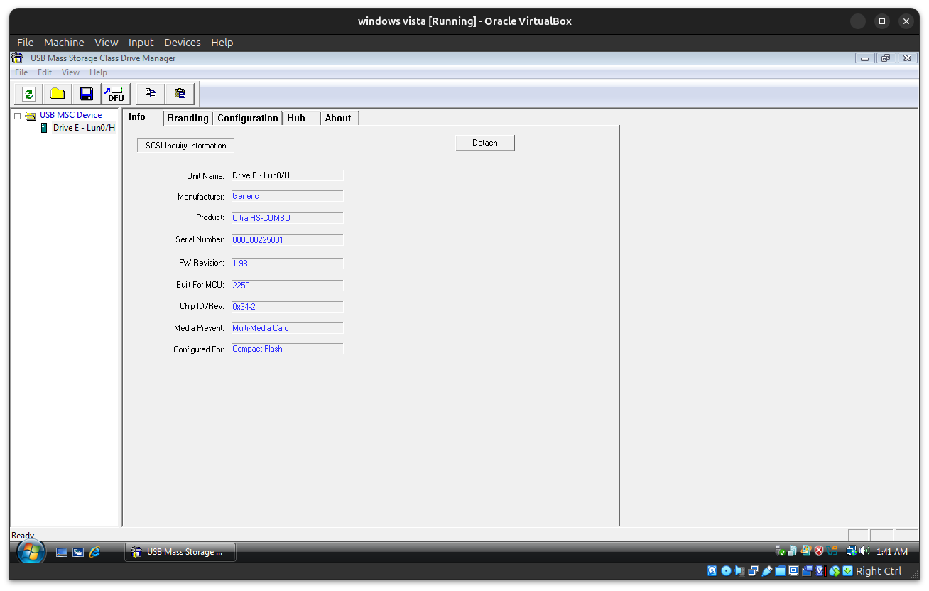
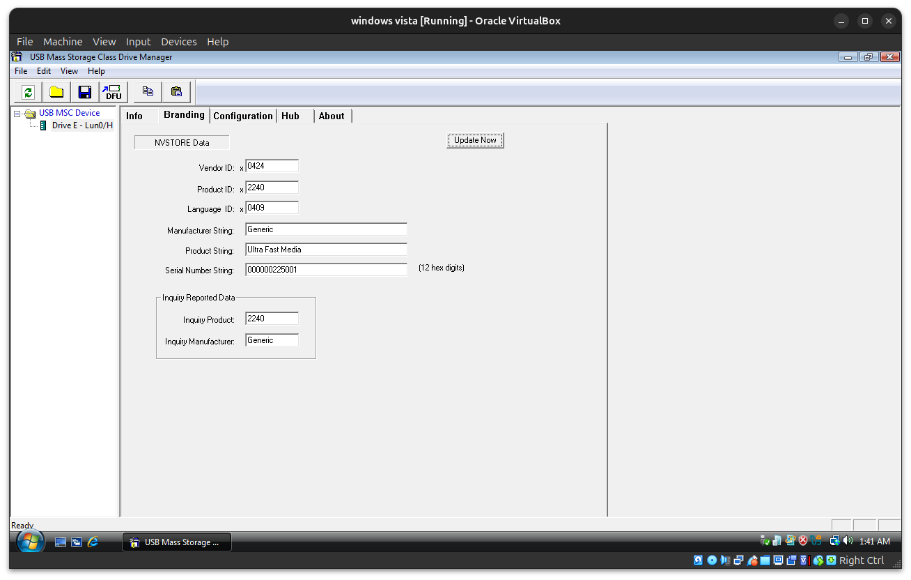
May change manufacturer, product description, VID, PID, etc. upon liking.
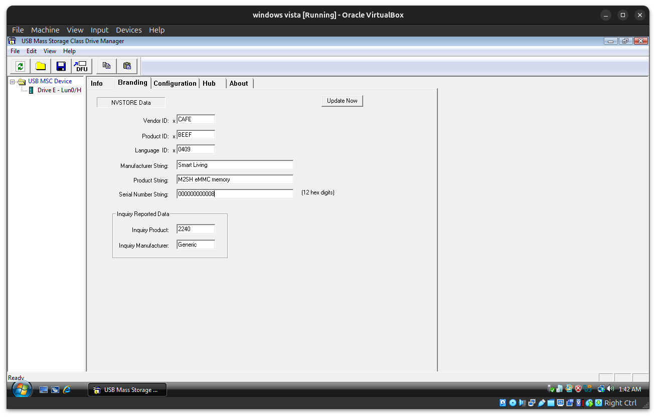
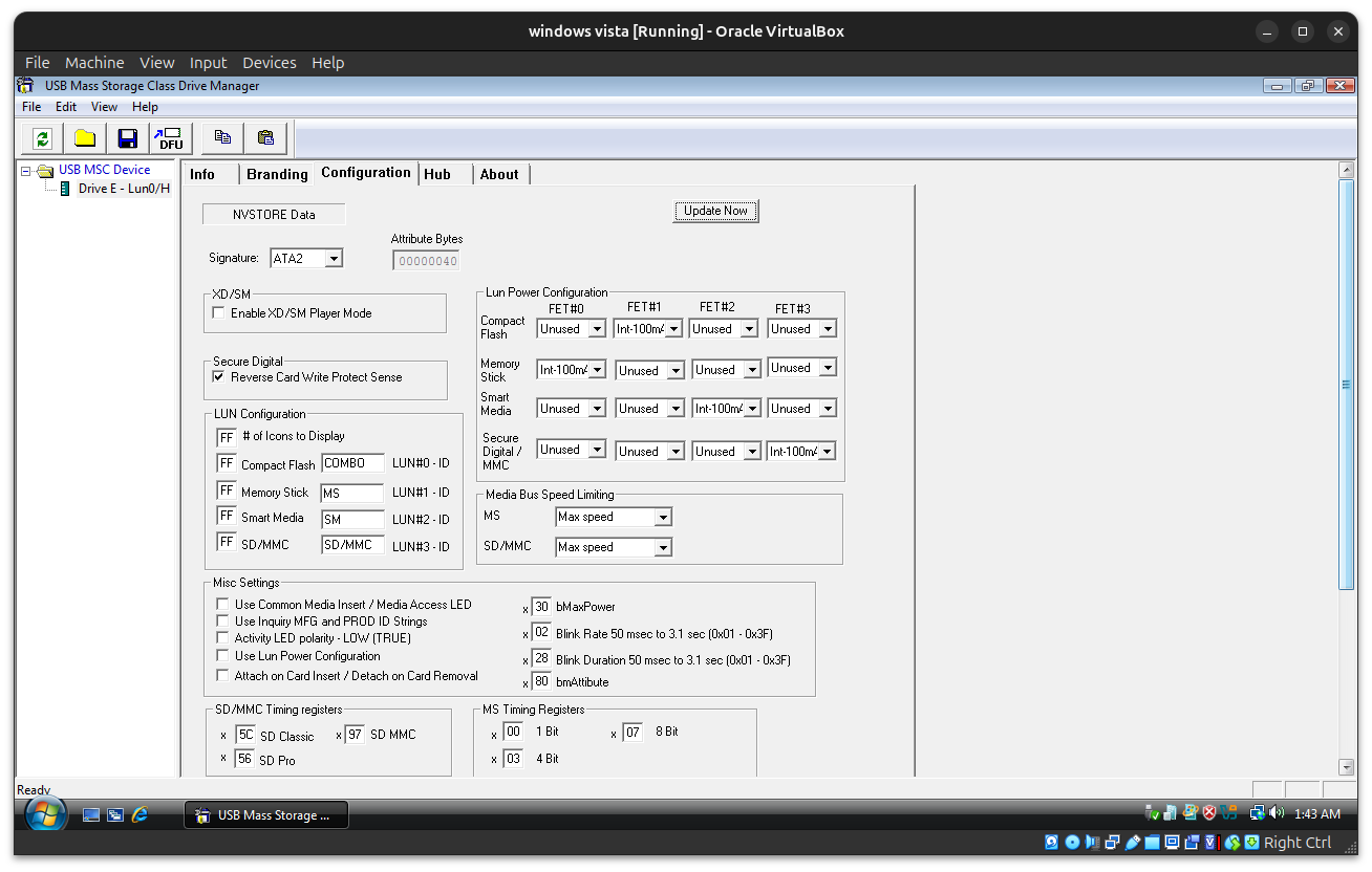
To flash it just click Update now
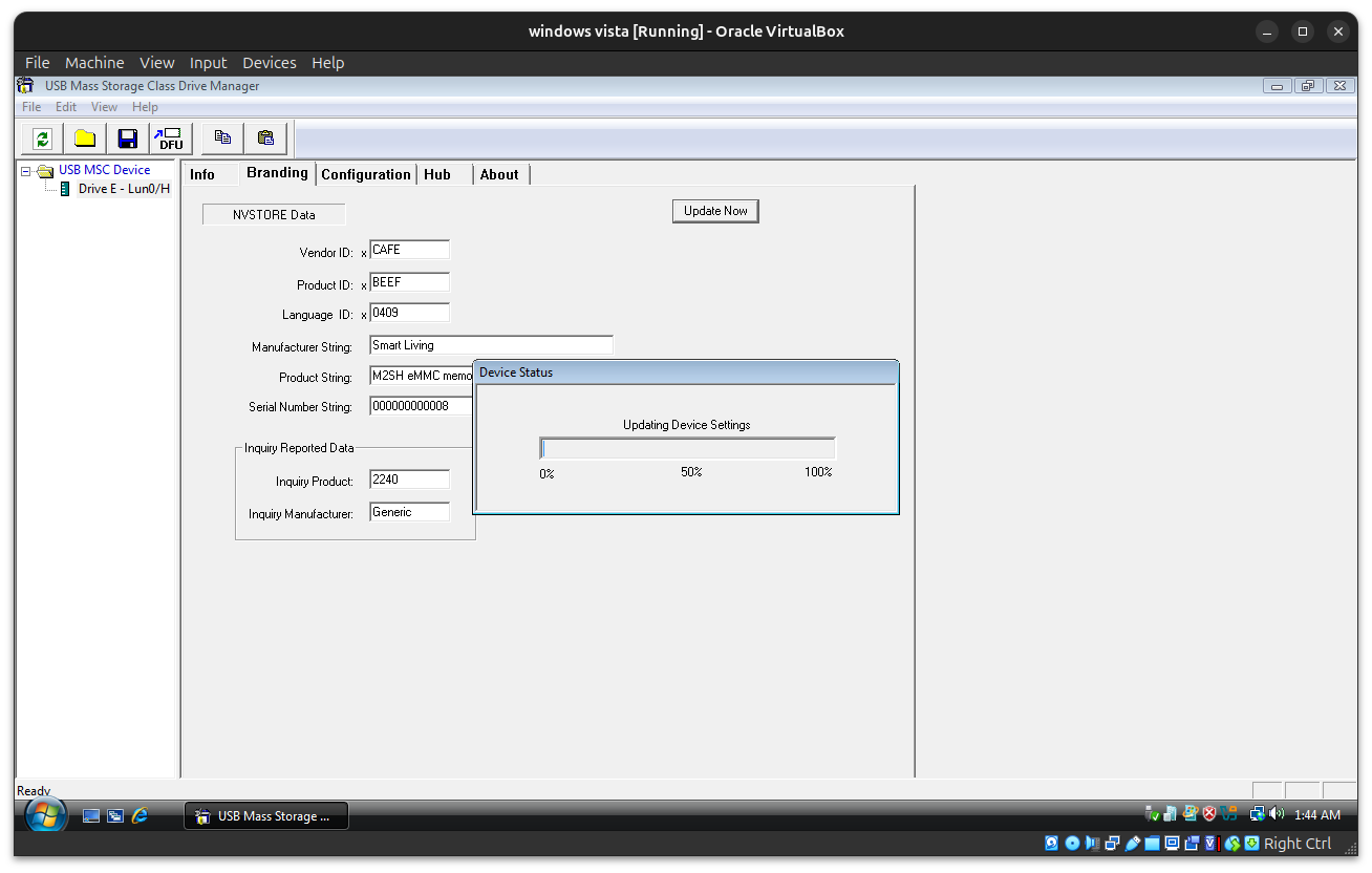
Similarly may modify settings for uSD card reader:
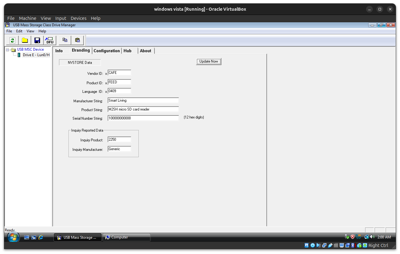
Requirements for this method:
To program eMMC controller - conenct TC2030 to J7 and for uSD to J8.
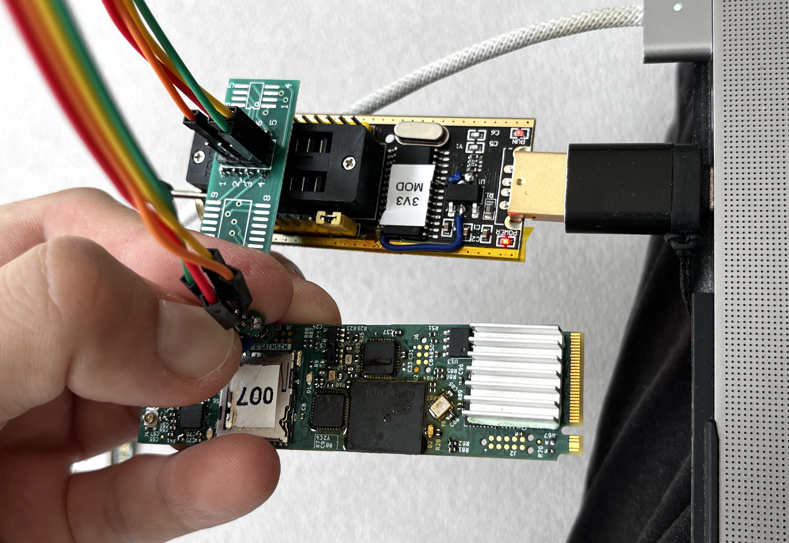
Binary files to be flashed located in firmware/eMMC_and_uSD/AsProgrammer:
usb2240_eeprom_m2sh_eMMC.binusb2240_eeprom_m2sh_uSD.binIn the application select I2C, choose IC->I2C->_24Cxxx->_24C04. Open provided file. To make any modification may do them right in the AsProgrammer window and as a reference use USB2240 datasheet.
To start programming click icon Unprotect -> erase -> program -> verify
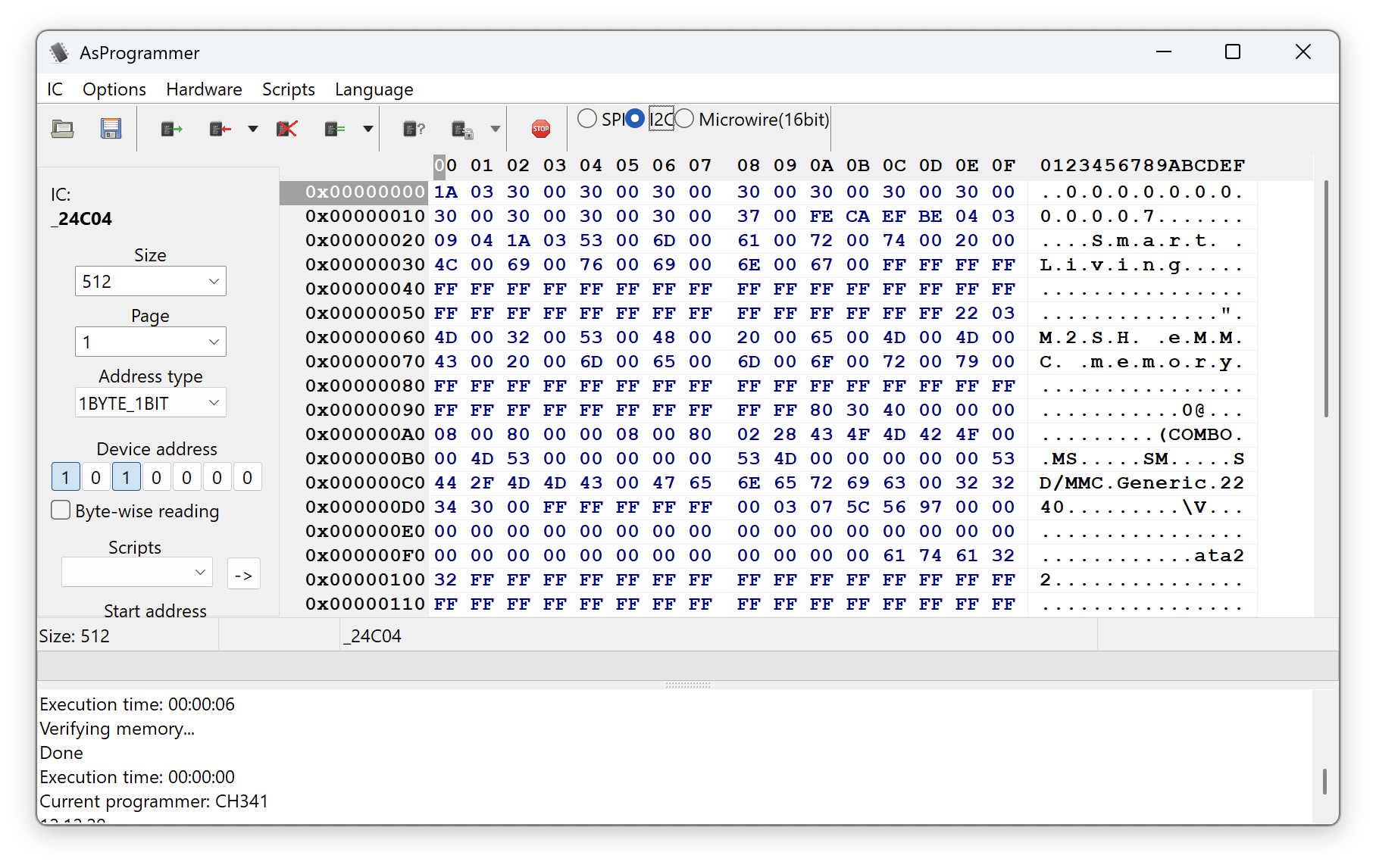
Thread radio uses CP2102n USB UART bridge which supports modification of USB parameters as VID, PID, manufacturer and product description. This gives oppurtinity to create own device not easily distinguished in the operating system as USB Serial bridge, rather as custom made piece of hardware. Provided by the manufacturer method of the modification is using Simplicity Studio and has been described in USBXpress™ Device Configuration and Programming Guide Due to fact Simplicity Studio is a full fledged IDE, for the customization used simple script cp210x-cfg from https://github.com/irrwisch1/cp210x-cfg. Worth to mention is the necessity of additional packages: sudo apt install build-essential libusb-1.0-0-dev
For this device customized only manufacturer string and product description as changing VID and PID would require creation of the custom device driver.
Checking for proper detection of the device:
sudo ./cp210x-cfg -l
ID 10c4:ea60 @ bus 003, dev 004: CP2102N USB to UART Bridge Controller
Change of the product description:
sudo ./cp210x-cfg -d 003.004 -N "M2SH Thread radio"
ID 10c4:ea60 @ bus 003, dev 004: CP2102N USB to UART Bridge Controller
Model: CP2102N QFN20
Vendor ID: 10c4
Product ID: ea60
Name: CP2102N USB to UART Bridge Controller
Manufacturer: Silicon Labs
Serial: 9ac4a9c38069ed11b176ea8cedc06881
Use internal serial: 1
ret: 678
IMPORTANT: Device needs to be replugged for some changes to take effect!
Change of the manufacturer name:
./cp210x-cfg -C 'Smart Living'
ID 10c4:ea60 @ bus 003, dev 004: M2SH Thread radio
Model: CP2102N QFN20
Vendor ID: 10c4
Product ID: ea60
Name: M2SH Thread radio
Manufacturer: Smart Living
Serial: 9ac4a9c38069ed11b176ea8cedc06881
Use internal serial: 1
ret: 678
After turn off of the PC and back on (CP2102n chip's power is not controlled from the USB HUB and cannot be toggled) those fields should be changed:
Bus 003 Device 004: ID 10c4:ea60 Silicon Labs CP210x UART Bridge
Device Descriptor:
  [...]
  idVendor           0x10c4 Silicon Labs
  idProduct          0xea60 CP210x UART Bridge
  bcdDevice            1.00
  iManufacturer           1 Smart Living
  iProduct                2 M2SH Thread radio
  iSerial                 3 9ac4a9c38069ed11b176ea8cedc06881
  [...]
To flash the firmware Segger J-Link Base programmer is necessary (supported by Simiplicity studio). For flashing bootloader used Simplicity commander. Bootloader and firmware used for test are from NabuCasa github release page
To flash bootloader power M2SH from external power supply (3V3 LDO output from segger j-link programmer may be not sufficient), connect TC2030 SWD cable to J9 connector on PCB. In simplicity commander under Device info chip should be detected.
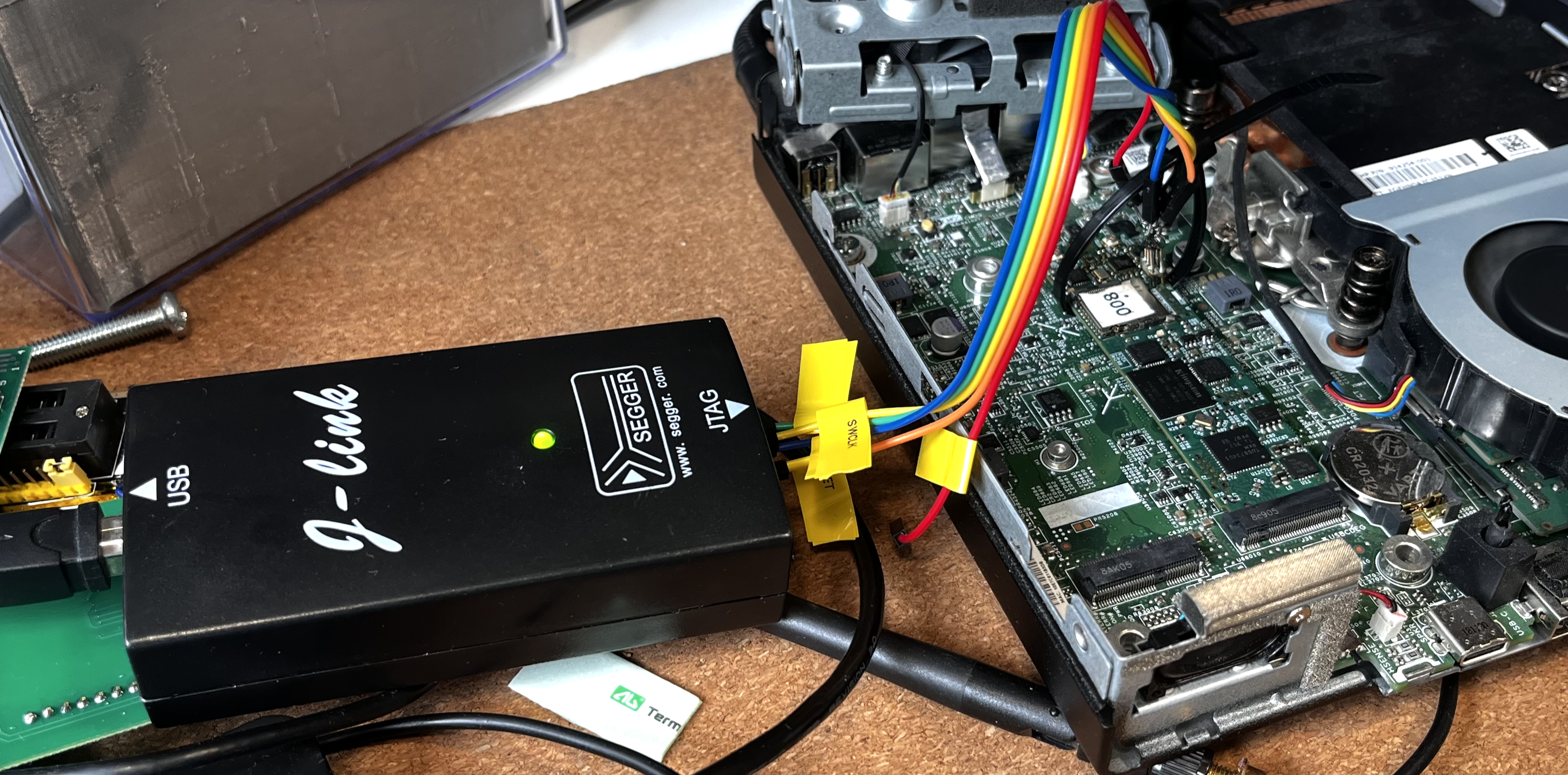
In the Flash tab select downloaded bootloader file, then click Flash
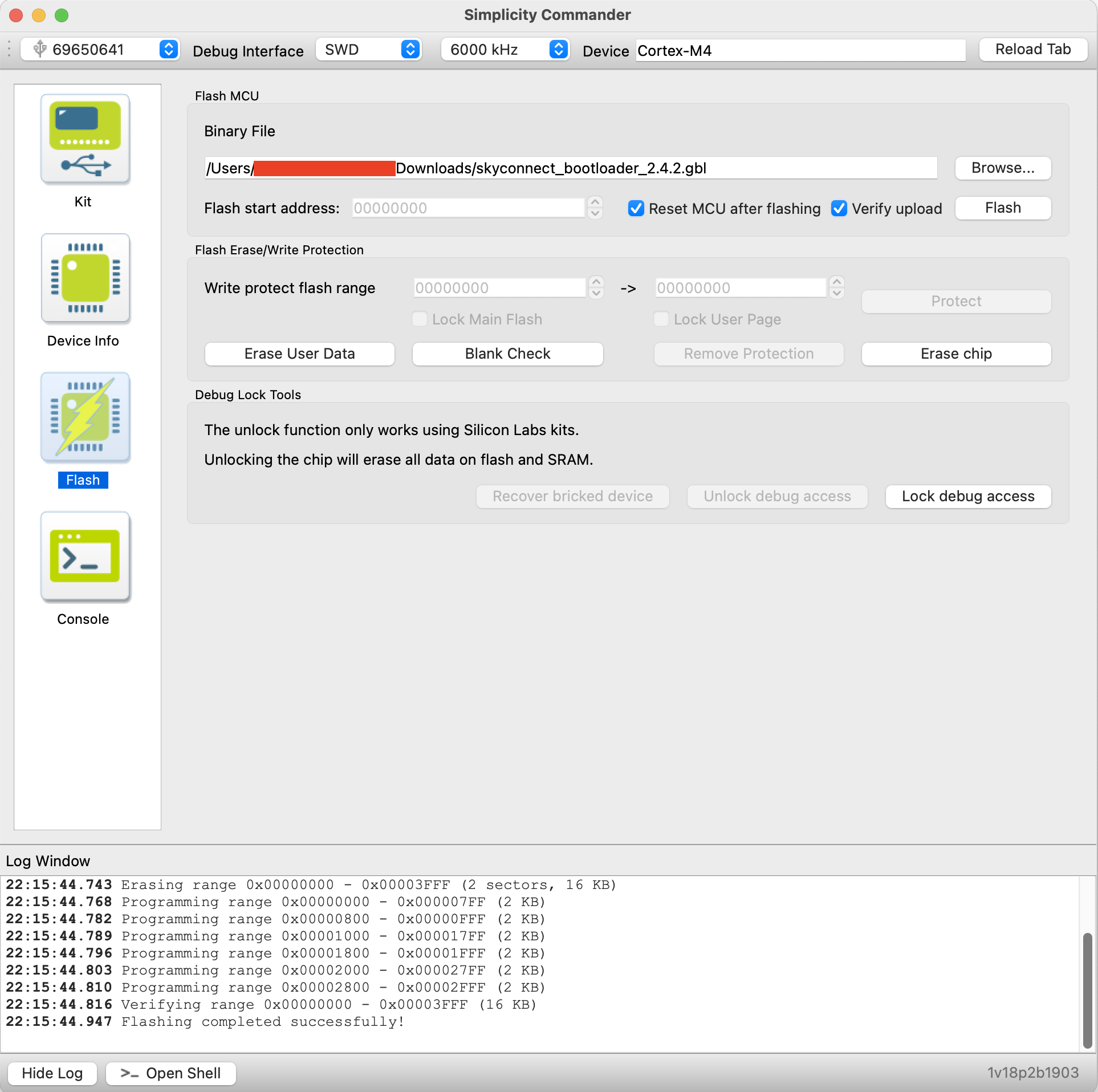
After successfull flash, when connecting to chip's UART (through present on M2SH CP2102n) bootloader should be shown those options:
Gecko Bootloader v2.04.02
1. upload gbl
2. run
3. ebl info
BL >
To flash firmware may send it via XModem (choose option 1 - upload gbl and send the firmware sx -X skyconnect_zigbee_ncp_7.4.4.1.gbl </dev/ttyUSB0 > /dev/ttyUSB0) or use Simplicity commander and flash it through SWD - select proper file and just press Flash.
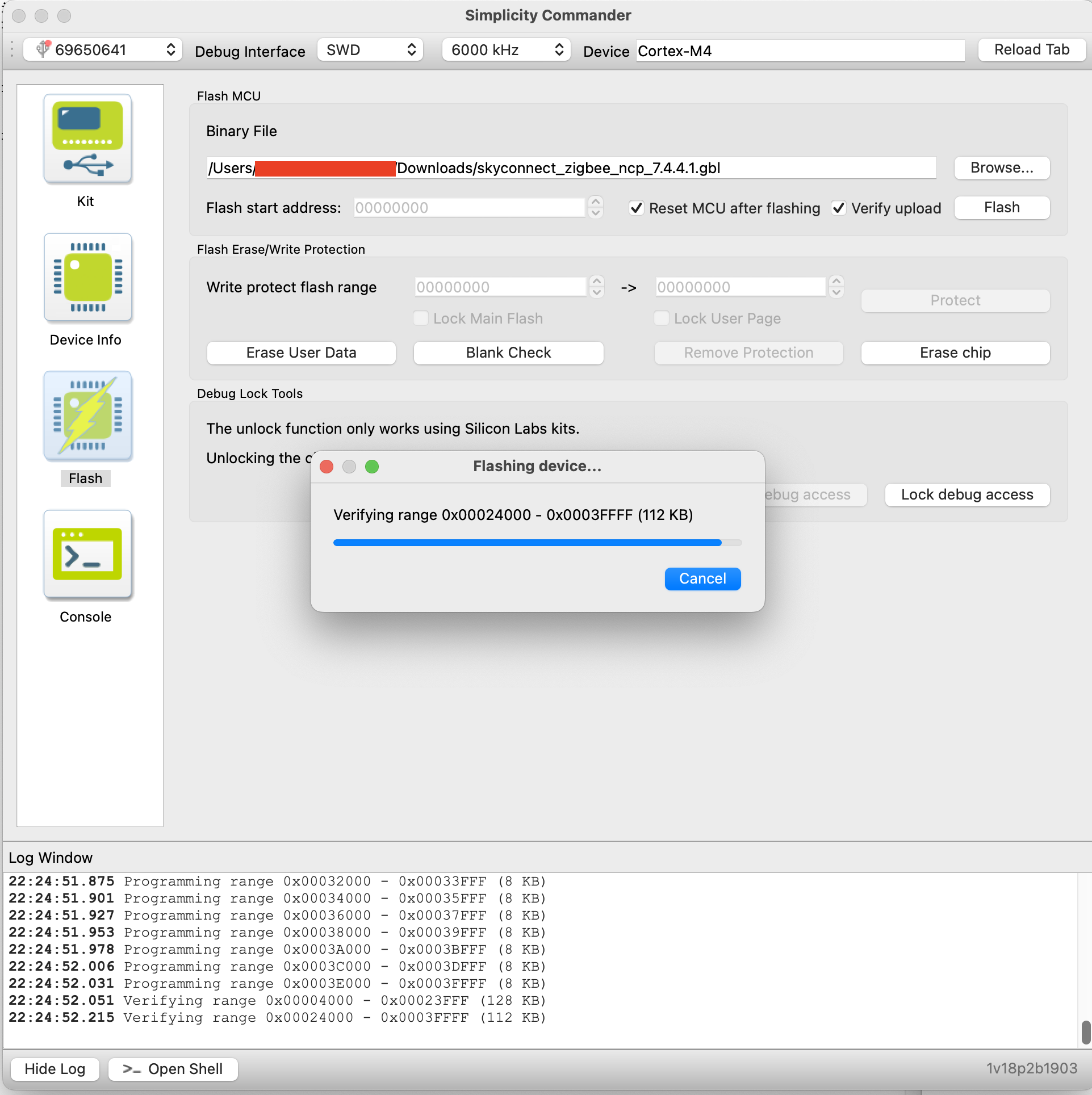
The brand-new RTL8188FTV chip comes unprogrammed, lacking both a MAC address and a serial number. Currently, it's not possible to flash its internal memory using any publicly available tools. The only known method to utilize this network card at the moment involves changing the MAC address directly within the driver, as detailed in the Wi-Fi bring-up section.
Below is a brief summary of the tools explored during the search for a suitable programming solution:
No source files were found for the RTL8188 driver, which previously served as the basis for leaked tools used in customizing network cards.
This repository contains the following directories:
hardware-electronics - Kicad 8 project (schematic, board and compontent library)images - contains photos and reders used in this READMEfirmware - contains flash binary files for custom devices configurations| Qty | Value | Footprint | References |
|---|---|---|---|
| 55 | C_100n_0402 | M2SmartHomeFootprints:C_0402 | C2, C3, C13, C15, C16, C19, C22, C24, C27, C29, C100, C101, C102, C103, C104, C105 +39 |
| 26 | R_0_0402 | M2SmartHomeFootprints:R_0402 | R3, R4, R10, R34, R48, R53, R54, R55, R58, R61, R63, R67, R68, R69, R70, R100 +10 |
| 22 | C_1uF_0402 | M2SmartHomeFootprints:C_0402 | C11, C12, C14, C17, C21, C26, C28, C30, C32, C34, C36, C37, C42, C43, C46, C55 +6 |
| 17 | R_4k7_0402 | M2SmartHomeFootprints:R_0402 | R5, R6, R23, R26, R31, R50, R51, R52, R56, R57, R59, R64, R76, R77, R90, R92 +1 |
| 16 | R_10k_0402 | M2SmartHomeFootprints:R_0402 | R1, R2, R19, R33, R37, R40, R42, R43, R44, R45, R46, R47, R49, R66, R78, R97 |
| 14 | R_49k9_0402 | M2SmartHomeFootprints:R_0402 | R11, R12, R13, R14, R15, R16, R17, R18, R20, R21, R22, R24, R25, R32 |
| 8 | R_27_0402 | M2SmartHomeFootprints:R_0402 | R81, R82, R83, R84, R85, R86, R87, R88 |
| 7 | C_4u7_0402 | M2SmartHomeFootprints:C_0402 | C18, C23, C35, C38, C40, C69, C71 |
| 6 | BSS138 | Package_TO_SOT_SMD:SOT-23 | Q2, Q3, Q4, Q5, Q6, Q7 |
| 6 | Fiducial | Fiducial:Fiducial_0.5mm_Mask1mm | FID1, FID2, FID3, FID4, FID5, FID6 |
| 4 | C_4pF_0402 | M2SmartHomeFootprints:C_0402 | C4, C10, C20, C25 |
| 4 | LED | M2SmartHomeFootprints:LED_KPT-1608ZGC | D1, D2, D3, D4 |
| 4 | R_510R_0402 | M2SmartHomeFootprints:R_0402 | R9, R27, R28, R38 |
| 4 | TC2030-IDC-NL | M2SmartHomeFootprints:TAG_TC2030-IDC-NL | J6, J7, J8, J9 |
| 4 | ~ | M2SmartHomeFootprints:TestPoint_Pad_D1.0mm | TP1, TP4, TP5, TP15 |
| 3 | C_22uF_10pct_10V_0603_C1608X5R1A226M080AC | M2SmartHomeFootprints:C_0603 | C1, C83, C95 |
| 3 | R_1M_0402 | M2SmartHomeFootprints:R_0402 | R8, R35, R89 |
| 2 | 24AA04T-I_OT | M2SmartHomeFootprints:24AA04T-I_OT | U4, U6 |
| 2 | CONMHF1-SMD-T | M2SmartHomeFootprints:CONMHF1-SMD-T | J3, J4 |
| 2 | C_0402_27p | M2SmartHomeFootprints:C_0402 | C67, C68 |
| 2 | C_0p9_0201 | M2SmartHomeFootprints:C_0201 | C53, C59 |
| 2 | C_10nF_5pct_50V_0402_C0402C103J5RACTU | M2SmartHomeFootprints:C_0402 | C70, C74 |
| 2 | C_12p_0402 | M2SmartHomeFootprints:C_0402 | C51, C52 |
| 2 | C_1nF_10pct_25V_0402_ KGM05AR71E102KH | M2SmartHomeFootprints:C_0402 | C106, C107 |
| 2 | C_1p9_0201 | M2SmartHomeFootprints:C_0201 | C54, C60 |
| 2 | C_33pF_5pct_50V_0402_C1005NP01H330J050BA | M2SmartHomeFootprints:C_0402 | C85, C86 |
| 2 | C_47n_0402 | M2SmartHomeFootprints:C_0402 | C49, C50 |
| 2 | ECS-240-10-47-CKM-TR | M2SmartHomeFootprints:ECS-240-10-47-CKM-TR | Y2, Y3 |
| 2 | L_2n1_0201 | M2SmartHomeFootprints:L_0201 | L3, L4 |
| 2 | L_9n1_0402 | M2SmartHomeFootprints:L_0402 | L1, L2 |
| 2 | R_12k_0402 | M2SmartHomeFootprints:R_0402 | R7, R36 |
| 2 | USB2244-AEZG-06 | M2SmartHomeFootprints:USB2244-AEZG-06 | U8, U9 |
| 1 | 24LC01B_SN | M2SmartHomeFootprints:24LC01B_SN | U13 |
| 1 | 2N7002 | M2SmartHomeFootprints:TRANS_2N7002 | Q1 |
| 1 | ABM8-38.400MHZ-10-D1G-T | M2SmartHomeFootprints:ABM8-38.400MHZ-10-D1G-T | Y4 |
| 1 | ABM8-40.000MHZ-B2-T | M2SmartHomeFootprints:ABM8-40.000MHZ-B2-T | Y5 |
| 1 | CP2102N-A02-GQFN20 | M2SmartHomeFootprints:CP2102N-A02-GQFN20 | U5 |
| 1 | ECS-480-18-33-JGN-TR | M2SmartHomeFootprints:ECS-480-18-33-JGN-TR | Y6 |
| 1 | EFR32MG21B020F1024IM32-B | M2SmartHomeFootprints:EFR32MG21B020F1024IM32-B | U7 |
| 1 | EMMC16G-MW28-01E10 | M2SmartHomeFootprints:EMMC16G-MW28-01E10 | U2 |
| 1 | FB_120R_0603 | M2SmartHomeFootprints:FB_0603 | FB2 |
| 1 | FB_220Ohm_600mA_0805_BLM21PG221SN1D | M2SmartHomeFootprints:FB_0805 | L5 |
| 1 | M.2-Key-M-edge-connector | M2SmartHomeFootprints:M.2-Key-M-edge-connector | J1 |
| 1 | Micro_SD_Card_Det_Hirose_DM3AT | M2SmartHomeFootprints:HRS_DM3AT-SF-PEJM5 | J5 |
| 1 | RTL8188FTV-VC-CG | M2SmartHomeFootprints:RTL8188FTV-VC-CG | U1 |
| 1 | R_100_0402 | M2SmartHomeFootprints:R_0402 | R71 |
| 1 | R_1k87_1pct_0402_CRCW04021K87FKED | M2SmartHomeFootprints:R_0402 | R39 |
| 1 | R_1k_0402 | M2SmartHomeFootprints:R_0402 | R29 |
| 1 | R_24k_0402 | M2SmartHomeFootprints:R_0402 | R41 |
| 1 | R_2k2_0402 | M2SmartHomeFootprints:R_0402 | R72 |
| 1 | R_47k5_0402 | M2SmartHomeFootprints:R_0402 | R30 |
| 1 | R_4k99_1pct_125mW_0402_CRCW04024K99FKEDHP | M2SmartHomeFootprints:R_0402 | R65 |
| 1 | R_9k09_1pct_0402_CRCW04029K09FKED | M2SmartHomeFootprints:R_0402 | R80 |
| 1 | TC2050-IDC-NL | M2SmartHomeFootprints:TAG-CONNECT_TC2050-IDC-NL | J2 |
| 1 | TPS74401RGWT | M2SmartHomeFootprints:TPS74401RGWT | U11 |
| 1 | TUSB7340IRKMT | M2SmartHomeFootprints:TUSB7340IRKMT | U12 |
ripclap/rm520n-carrier
KiCad RM520N-GL carrier with 2.5 GbE, passive PoE, dual SIM interfaces and independent LoRa management.


BerkeleyLab/Marble
Dual FMC FPGA carrier board developed for general purpose use in particle accelerator electronics instrumentation.


christianarrer/crawler-pi-hardware
Contains electronic PCB designs and 3D-printable parts for the crawler-pi autonomous tracked robot. Copy
It measures 22 × 80 mm and has 6 copper layers, 0.85 mm thick.
257 parts, built around the EFR32MG21B020F1024IM32-B, RTL8188FTV-VC-CG, USB2244-AEZG-06 and CP2102N-A02-GQFN20. The full list of its parts is on this page, with links to each part's symbol and footprint where PCBKit's library has them.
From the lukasznowarkiewicz/M2SmartHome repository on GitHub, at the commit this page was made from: the board is hardware-electronics/M2SmartHome.kicad_pcb and its schematic hardware-electronics/M2SmartHome.kicad_sch. PCBKit opens the board in the browser, with nothing to install.
Its repository states no licence, so its author keeps all rights: ask lukasznowarkiewicz before reusing the design.