
2 layers83.3 × 65.3 mm
SimonShield
github-linguist/linguist
Language Savant. If your repository's language is being reported incorrectly, send us a pull request!
46 parts14kMIT

 lukaszjesko/Smart-Access-Control
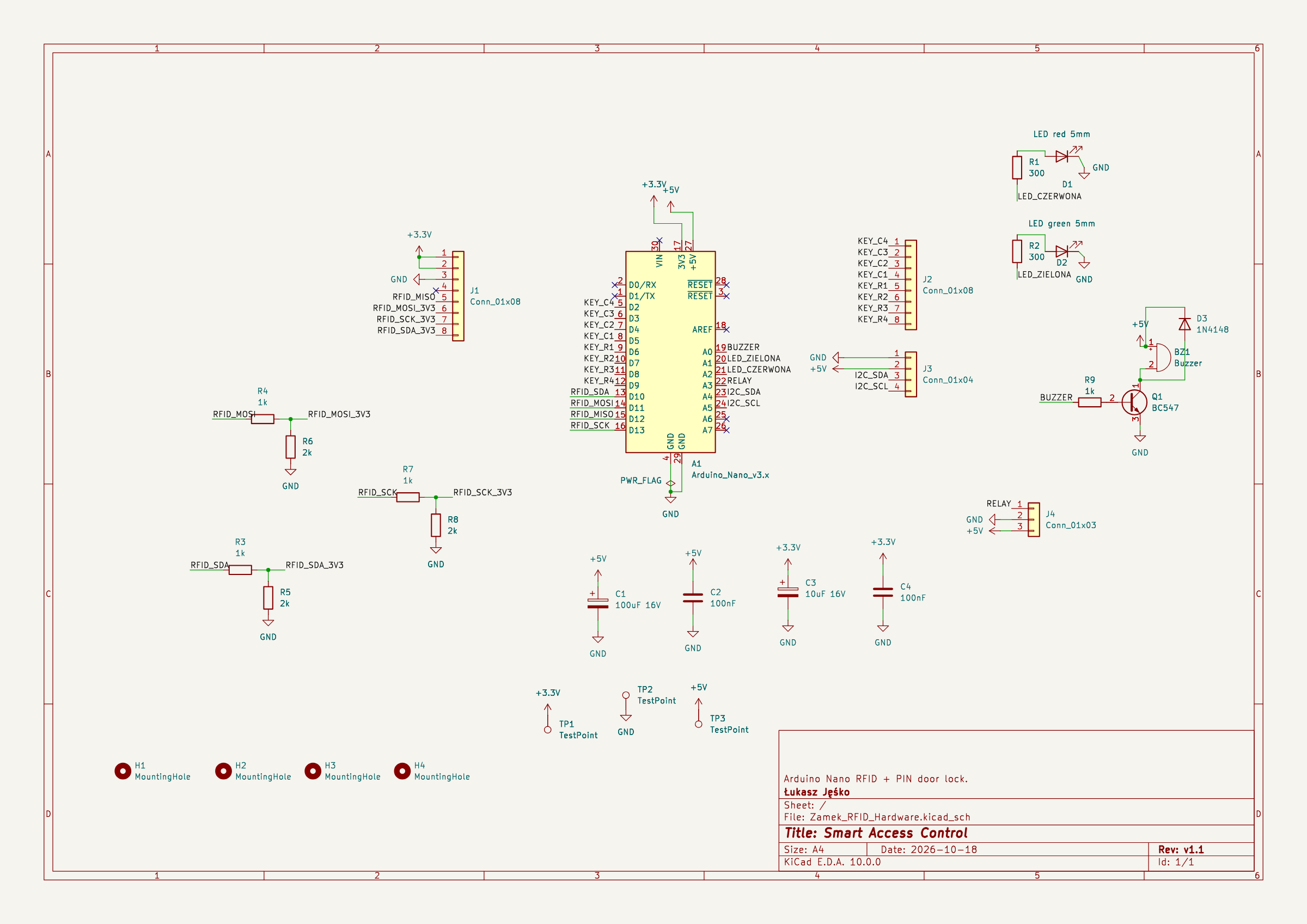
A door lock controller on my own PCB. To open the door you need the right RFID card and the right 4-digit PIN. An Arduino Nano checks both and switches a 12 V door strike through a relay.
Zamek RFID Hardware is an open-source printed circuit board by lukaszjesko, from the lukaszjesko/Smart-Access-Control repository on GitHub, published under the MIT licence. It is a 2-layer board of 72 × 57.2 mm with 30 parts on 37 nets, routed with 96 tracks and 0 vias.
It is built around the BC547. Its parts include 9 resistors, 4 capacitors, 4 connectors, 3 diodes and 1 transistor. It belongs with the radio and wireless boards and the AVR (ATmega, ATtiny) boards of this library.
A door lock controller on my own PCB. To open the door you need the right RFID card and the right 4-digit PIN. An Arduino Nano checks both and switches a 12 V door strike through a relay.
| KiCad 3D render | Assembled board |
|---|---|
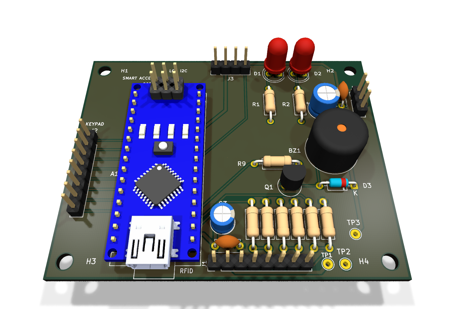 | 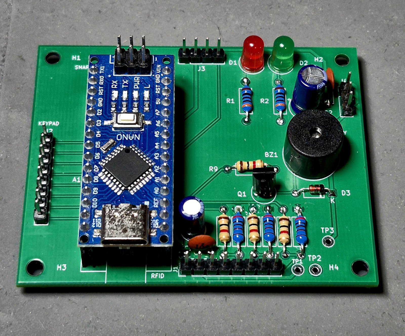 |
This is the first PCB I designed and ordered. I drew v1.0 in KiCad, found a lot of mistakes during a review, fixed them in v1.1 and ordered v1.1 from JLCPCB.
Arduino Nano, MFRC522 RFID reader (as a module on a header), 4x4 keypad, 16x2 LCD over I2C, relay module, buzzer and two LEDs.
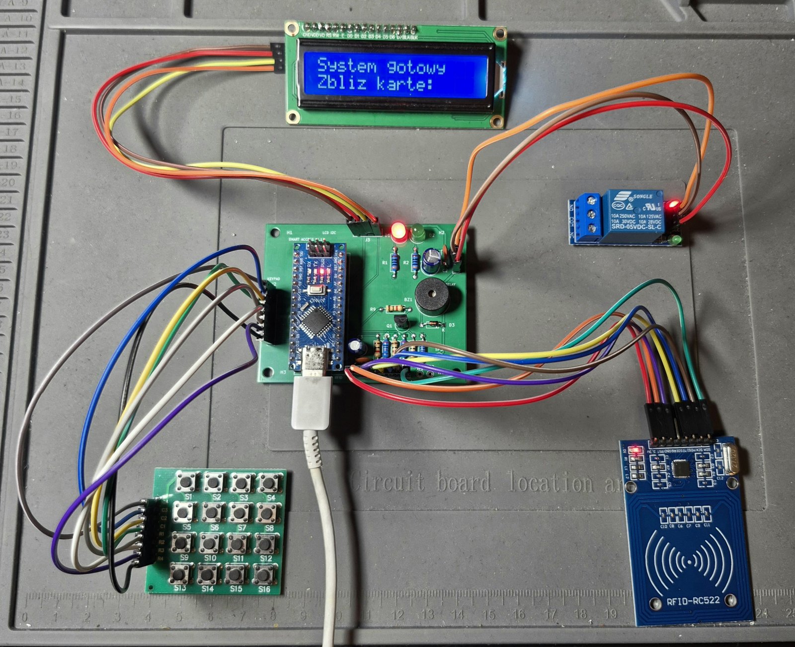
The firmware is a simple state machine: wait for a card, wait for the PIN, open or deny, then back to waiting.
| Routing (ground pour hidden) | All copper layers |
|---|---|
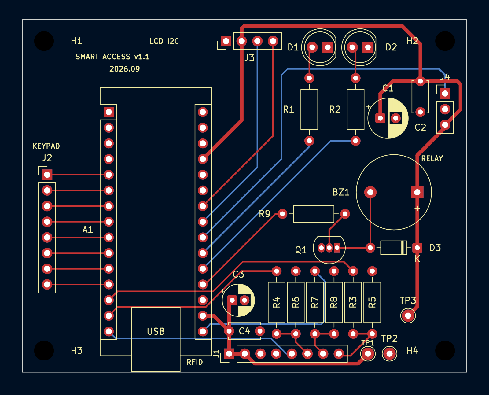 | 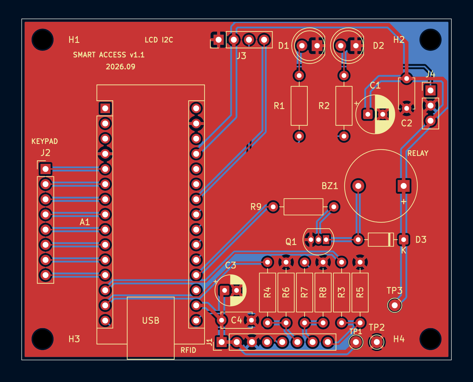 |
Red = top copper, blue = bottom copper. On the left the ground pour is hidden so the tracks are visible.
Schematic as PDF: docs/schematic_v1.1.pdf. KiCad project: Zamek_RFID_Hardware/.
The relay module is active LOW, so at power-up the door opened for a split second
before the program set the pin. Writing HIGH to the pin before pinMode() fixed it.
String with a char buffer, replace delay() with millis(),
lock the keypad after 5 wrong PINsPlatformIO, target nanoatmega328new:
cp include/config.example.h include/config.h   # set your card UID and PIN
pio run --target uploadFirmware: MIT. Hardware: CERN-OHL-S-2.0.
| Qty | Value | Footprint | References |
|---|---|---|---|
| 4 | 1k | Resistor_THT:R_Axial_DIN0207_L6.3mm_D2.5mm_P10.16mm_Horizontal | R3, R4, R7, R9 |
| 4 | MountingHole | MountingHole:MountingHole_3.2mm_M3 | H1, H2, H3, H4 |
| 3 | 2k | Resistor_THT:R_Axial_DIN0207_L6.3mm_D2.5mm_P10.16mm_Horizontal | R5, R6, R8 |
| 3 | TestPoint | TestPoint:TestPoint_THTPad_D2.0mm_Drill1.0mm | TP1, TP2, TP3 |
| 2 | 100nF | Capacitor_THT:C_Disc_D5.0mm_W2.5mm_P5.00mm | C2, C4 |
| 2 | 300 | Resistor_THT:R_Axial_DIN0207_L6.3mm_D2.5mm_P10.16mm_Horizontal | R1, R2 |
| 2 | Conn_01x08 | Connector_PinHeader_2.54mm:PinHeader_1x08_P2.54mm_Vertical | J1, J2 |
| 1 | 100uF 16V | Capacitor_THT:CP_Radial_D6.3mm_P2.50mm | C1 |
| 1 | 10uF 16V | Capacitor_THT:CP_Radial_D5.0mm_P2.00mm | C3 |
| 1 | 1N4148 | Diode_THT:D_DO-35_SOD27_P7.62mm_Horizontal | D3 |
| 1 | Arduino_Nano_v3.x | Module:Arduino_Nano | A1 |
| 1 | BC547 | Package_TO_SOT_THT:TO-92_Inline | Q1 |
| 1 | Buzzer | Buzzer_Beeper:Buzzer_12x9.5RM7.6 | BZ1 |
| 1 | Conn_01x03 | Connector_PinHeader_2.54mm:PinHeader_1x03_P2.54mm_Vertical | J4 |
| 1 | Conn_01x04 | Connector_PinHeader_2.54mm:PinHeader_1x04_P2.54mm_Vertical | J3 |
| 1 | LED green 5mm | LED_THT:LED_D5.0mm | D2 |
| 1 | LED red 5mm | LED_THT:LED_D5.0mm | D1 |
github-linguist/linguist
Language Savant. If your repository's language is being reported incorrectly, send us a pull request!

dotnet/iot
This repo includes .NET Core implementations for various IoT boards, chips, displays and PCBs.

peterheinrich/InternetOverSpaghetti
Transmitting IP packages over a pair of spaghetti thus demonstrating how media independent IP really is.

tebl/RC6502-Apple-1-Replica
An expandable SBC-version of the Apple 1 computer, easy to get started with and lot of cool stuff that can be added to it!


ZeroPhone/ZeroPhone-PCBs
PCB files for ZeroPhone - for gerbers and schematics, go to "Releases" tab!

It measures 72 × 57.2 mm and has 2 copper layers, 1.6 mm thick.
30 parts, built around the BC547. The full list of its parts is on this page, with links to each part's symbol and footprint where PCBKit's library has them.
From the lukaszjesko/Smart-Access-Control repository on GitHub, at the commit this page was made from: the board is Zamek_RFID_Hardware/Zamek_RFID_Hardware/Zamek_RFID_Hardware.kicad_pcb and its schematic Zamek_RFID_Hardware/Zamek_RFID_Hardware/Zamek_RFID_Hardware.kicad_sch. PCBKit opens the board in the browser, with nothing to install.
Its repository publishes it under the MIT licence: you may reuse it on that licence's terms (keep the author's notice, and for a copyleft licence share your changes alike).