A modular development kit for the Electrosmith Daisy Seed development board. Currently modules include the central breakout board, a MIDI adapter and an array of 16 potentiometers.
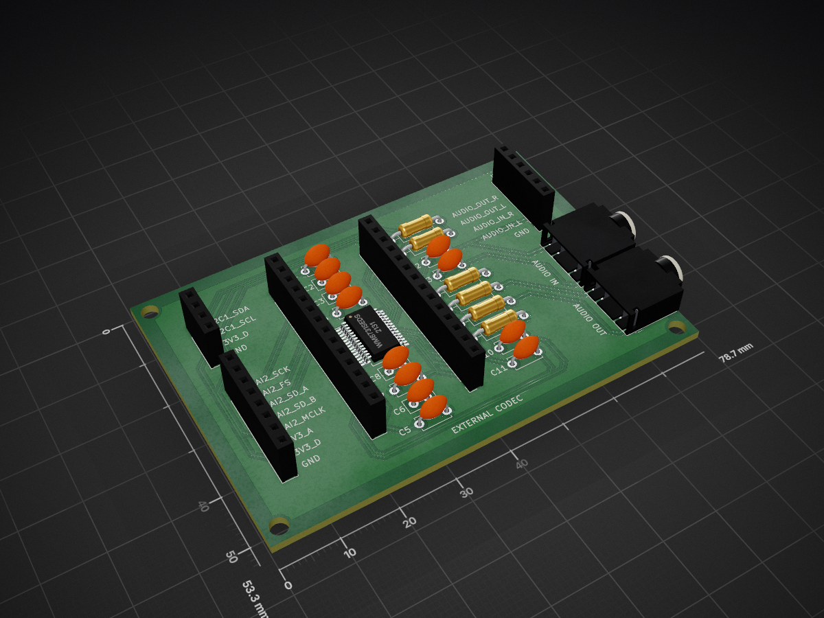
ExternalCodec is an open-source printed circuit board by lucidcoding, from the lucidcoding/daisy-seed-development-kit repository on GitHub. It is a 2-layer board of 78.7 × 53.3 mm with 26 parts on 29 nets, routed with 251 tracks and 0 vias.
It is built around the WM8731SEDS. Its parts include 12 capacitors, 7 connectors, 6 resistors and 1 IC.
A modular development kit for the Electrosmith Daisy Seed development board. Currently modules include the central breakout board, a MIDI adapter and an array of 16 potentiometers. The breakout board includes connections for a second potentiometer array, SPI, I2C, an encoder and an SD card.
Environment Setup
Ensure you have LIBDAISY_DIR and DAISYSP_DIR environment variables set and pointing to the relevant libraries. If you are using Windows, ensure they use the forward slash. If you are on Linux, ensure the capitalisation is correct. You'll make your life a lot easier if you don't have spaces in the path:
In order to build the hardware, load each of the projects in to Kicad, generate Gerber files and upload to a PCB manufacturer such as https://jlcpcb.com/. I can go into more detail about this at a later point.
The to get started, load the MonoSeed09 project on to the Daisy Seed by pressing both buttons to put it into program mode, entering the relevant folder, then enetering the commands to upload the code onto the Seed:
text
cd Examples/MonoSeed09
make clean; make; make program-dfu;
Ensure the Daisy Seed is correctly seated in the breakout board. Then connect the potentiometer array to port 1 with a JST XH2.54 8 wire cable, and connect the MIDI adapter with a JST XH2.54 4 wire cable. Finally connect your MIDI sequencer to the MIDI in DIN connector and plug your headphones into the audio out jack socket. Set the MIDI transmit channel to 1 - this is what it defaults to.
Disclaimer
Although I am a professional programmer, I am purely a hobbyist when it comes to hardware or embedded programming. There may well be some mistakes here and I accept no responsibility for damage to you Daisy Seed, external equipment or anything else. You use this code and harware at your own risk.
It measures 78.7 × 53.3 mm and has 2 copper layers, 1.6 mm thick.
What parts does the ExternalCodec use?
26 parts, built around the WM8731SEDS. The full list of its parts is on this page, with links to each part's symbol and footprint where PCBKit's library has them.
Where can I download the ExternalCodec KiCad files?
From the lucidcoding/daisy-seed-development-kit repository on GitHub, at the commit this page was made from: the board is Hardware/ExternalCodec/PCB/ExternalCodec/ExternalCodec.kicad_pcb and its schematic Hardware/BreakoutBoard/PCB/BreakoutBoard/BreakoutBoard.kicad_sch. PCBKit opens the board in the browser, with nothing to install.
Can I use the ExternalCodec design in my own project?
Its repository states no licence, so its author keeps all rights: ask lucidcoding before reusing the design.
A modular development kit for the Electrosmith Daisy Seed development board. Currently modules include the central breakout board, a MIDI adapter and an array of 16 potentiometers.
A modular development kit for the Electrosmith Daisy Seed development board. Currently modules include the central breakout board, a MIDI adapter and an array of 16 potentiometers.
A modular development kit for the Electrosmith Daisy Seed development board. Currently modules include the central breakout board, a MIDI adapter and an array of 16 potentiometers.