2 layers134.6 × 106.4 mm
Renovation ssi 2001
roybaer/renovation_ssi_2001
Innovation SSI-2001 replica that can be built without vintage components
95 parts26

 lucaci32u4/ExED
Extended Digital Electronics Laboratory
ExED is an open-source printed circuit board by lucaci32u4, from the lucaci32u4/ExED repository on GitHub, published under the GPL-3.0 licence. It is a 2-layer board of 117.2 × 115.1 mm with 136 parts on 112 nets, routed with 718 tracks and 54 vias.
It is built around the NE555P, 74HC595 and 74LS00SC, with the PN2222A among its other parts. Its parts include 69 resistors, 22 diodes, 19 capacitors, 15 connectors and 7 ICs.


This laboratory is intended to be used as teaching material for the 6th Digital Electronics laboratory in the Faculty of Computer Science, Politehnica University of Bucharest.
This laboratory material presents the functioning of a shift register, a ring counter and a phase-locked loop. The following applications can be built:
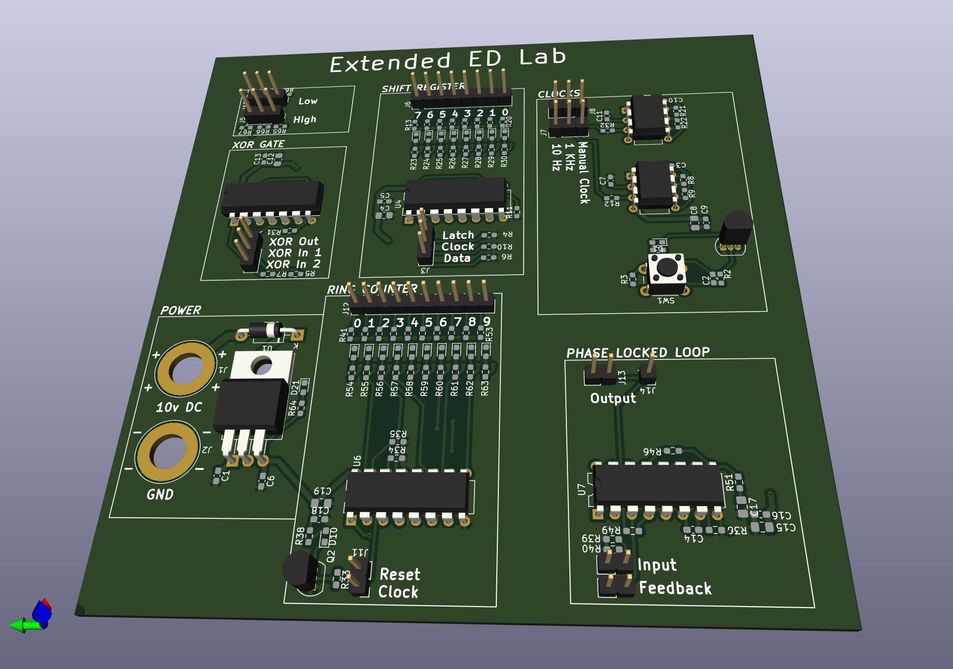
A batch of 10 boards v0.01 were built. Seven of them were populated and tested in field, while three were kept for archieval purposes.
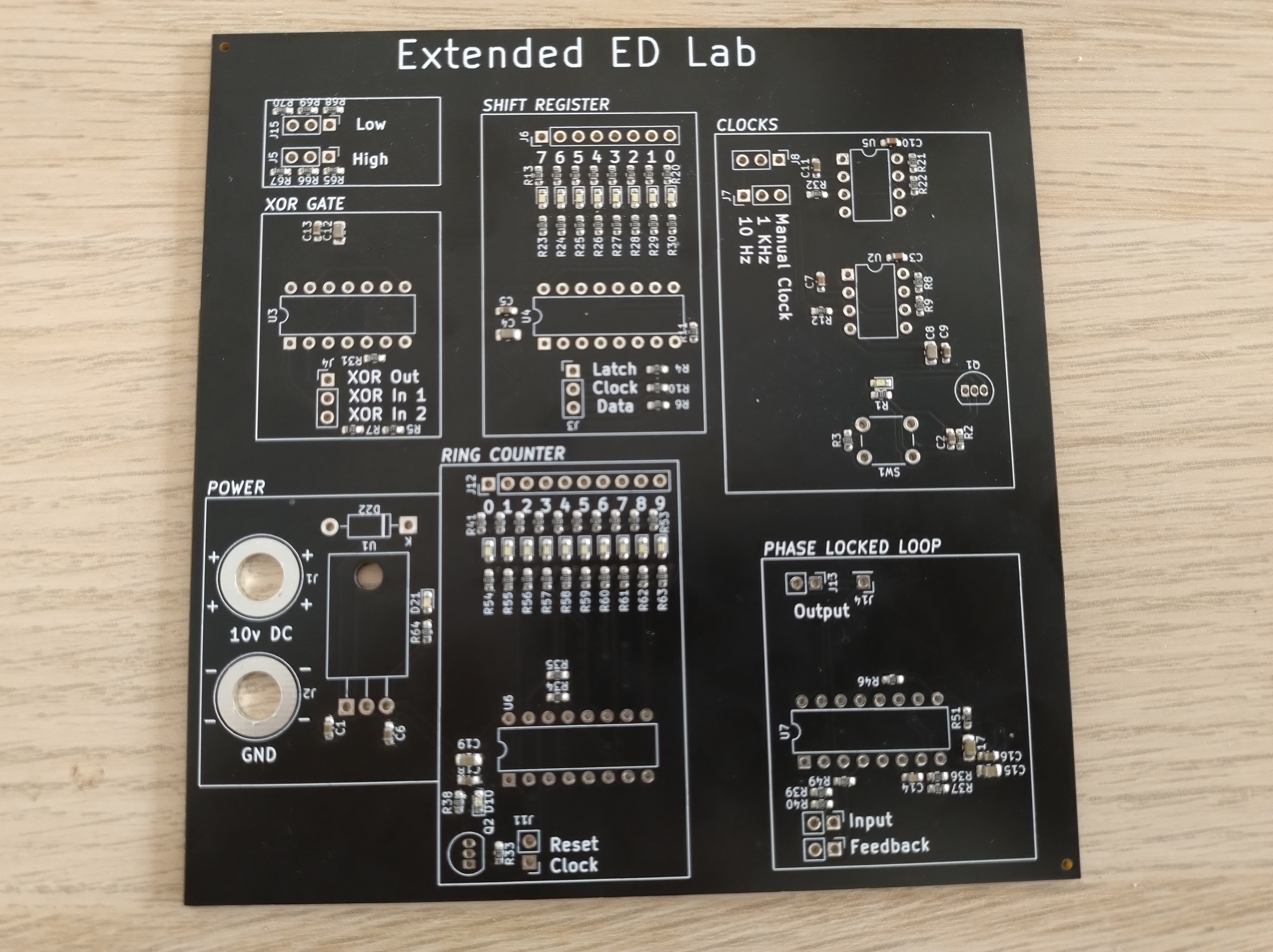
After teaching the extended laboratory to two groups, the following observations can be made:
These flaws are planned to be fixed in version v0.2.
| Qty | Value | Footprint | References |
|---|---|---|---|
| 28 | 100 | Resistor_SMD:R_0603_1608Metric_Pad0.98x0.95mm_HandSolder | R12, R13, R14, R15, R16, R17, R18, R19, R20, R31, R32, R41, R42, R43, R44, R45 +12 |
| 22 | 330 | Resistor_SMD:R_0603_1608Metric_Pad0.98x0.95mm_HandSolder | R1, R3, R23, R24, R25, R26, R27, R28, R29, R30, R38, R54, R55, R56, R57, R58 +6 |
| 21 | LED | LED_SMD:LED_0603_1608Metric_Pad1.05x0.95mm_HandSolder | D1, D2, D3, D4, D10, D11, D12, D13, D14, D15, D16, D17, D18, D19, D20, D21 +5 |
| 11 | 10k | Resistor_SMD:R_0603_1608Metric_Pad0.98x0.95mm_HandSolder | R4, R5, R6, R7, R10, R11, R34, R35, R39, R40, R51 |
| 9 | 1u | Capacitor_SMD:C_0603_1608Metric_Pad1.08x0.95mm_HandSolder | C1, C2, C5, C6, C9, C11, C13, C16, C18 |
| 6 | 100n | Capacitor_SMD:C_0805_2012Metric_Pad1.18x1.45mm_HandSolder | C4, C8, C12, C15, C17, C19 |
| 4 | 47k | Resistor_SMD:R_0603_1608Metric_Pad0.98x0.95mm_HandSolder | R8, R9, R21, R22 |
| 3 | 10n | Capacitor_SMD:C_0603_1608Metric_Pad1.08x0.95mm_HandSolder | C3, C7, C10 |
| 2 | 100k | Resistor_SMD:R_0603_1608Metric_Pad0.98x0.95mm_HandSolder | R36, R46 |
| 2 | 1k | Resistor_SMD:R_0603_1608Metric_Pad0.98x0.95mm_HandSolder | R2, R33 |
| 2 | Clocks | Connector_PinHeader_2.54mm:PinHeader_1x03_P2.54mm_Vertical | J7, J8 |
| 2 | NE555P | Package_DIP:DIP-8_W7.62mm | U2, U5 |
| 2 | PLLDivider | Connector_PinHeader_2.54mm:PinHeader_1x02_P2.54mm_Vertical | J9, J10 |
| 2 | PN2222A | Package_TO_SOT_THT:TO-92_Inline | Q1, Q2 |
| 1 | 1N4001 | Diode_THT:D_DO-41_SOD81_P10.16mm_Horizontal | D22 |
| 1 | 1nF | Capacitor_SMD:C_0603_1608Metric_Pad1.08x0.95mm_HandSolder | C14 |
| 1 | 4017 | Package_DIP:DIP-16_W7.62mm | U6 |
| 1 | 4046 | Package_DIP:DIP-16_W7.62mm | U7 |
| 1 | 74HC595 | Package_DIP:DIP-16_W7.62mm | U4 |
| 1 | 74LS00 | Package_DIP:DIP-14_W7.62mm | U3 |
| 1 | BananaMinus | Connector:Banana_Jack_1Pin | J2 |
| 1 | BananaPlus | Connector:Banana_Jack_1Pin | J1 |
| 1 | CounterControl | Connector_PinHeader_2.54mm:PinHeader_1x02_P2.54mm_Vertical | J11 |
| 1 | CounterOutput | Connector_PinHeader_2.54mm:PinHeader_1x10_P2.54mm_Vertical | J12 |
| 1 | LM7805_TO220 | Package_TO_SOT_THT:TO-220-3_Horizontal_TabDown | U1 |
| 1 | LOGO | LOGO | G*** |
| 1 | LogicHigh | Connector_PinHeader_2.54mm:PinHeader_1x03_P2.54mm_Vertical | J5 |
| 1 | LogicLow | Connector_PinHeader_2.54mm:PinHeader_1x03_P2.54mm_Vertical | J15 |
| 1 | Manual | Button_Switch_THT:SW_PUSH_6mm | SW1 |
| 1 | PLLOutput | Connector_PinHeader_2.54mm:PinHeader_1x01_P2.54mm_Vertical | J14 |
| 1 | PLLOutput | Connector_PinHeader_2.54mm:PinHeader_1x02_P2.54mm_Vertical | J13 |
| 1 | ShiftInput | Connector_PinHeader_2.54mm:PinHeader_1x03_P2.54mm_Vertical | J3 |
| 1 | ShiftOutput | Connector_PinHeader_2.54mm:PinHeader_1x08_P2.54mm_Vertical | J6 |
| 1 | XOR | Connector_PinHeader_2.54mm:PinHeader_1x03_P2.54mm_Vertical | J4 |
It measures 117.2 × 115.1 mm and has 2 copper layers, 1.6 mm thick.
136 parts, built around the NE555P, 74HC595, 74LS00SC and PN2222A. The full list of its parts is on this page, with links to each part's symbol and footprint where PCBKit's library has them.
From the lucaci32u4/ExED repository on GitHub, at the commit this page was made from: the board is Schematic/exed.kicad_pcb and its schematic Schematic/exed.kicad_sch. PCBKit opens the board in the browser, with nothing to install.
Its repository publishes it under the GPL-3.0 licence: you may reuse it on that licence's terms (keep the author's notice, and for a copyleft licence share your changes alike).
roybaer/renovation_ssi_2001
Innovation SSI-2001 replica that can be built without vintage components

sladek/SBC_8080_ECB
This is my attempt to build a single-board microcomputer based on the Intel 8080 CPU. It contains the following features:


gpimblott/ZX81-Composite-mod-PCB
PCB that implements the ZX81 composite mod including the backporch signal for older versions

elamrobert443/alternating-led-heart-pcb
Custom KiCad PCB featuring alternating red and white LED arrays driven by a 555 timer and transistor switching circuits.

f5vmr/QRM_Eliminator
A mistake in the downloaded zip file!! The PCB is not designed with Diptrace but with KiCad and the version it was made with can be down loaded free from here -…

jakeson21/Small-KiCAD-Projects
Collection of one-off KiCAD projects
