
2 layers
 loudifier/OpenRefMic169
open hardware design for a high-performance low-cost measurement microphone
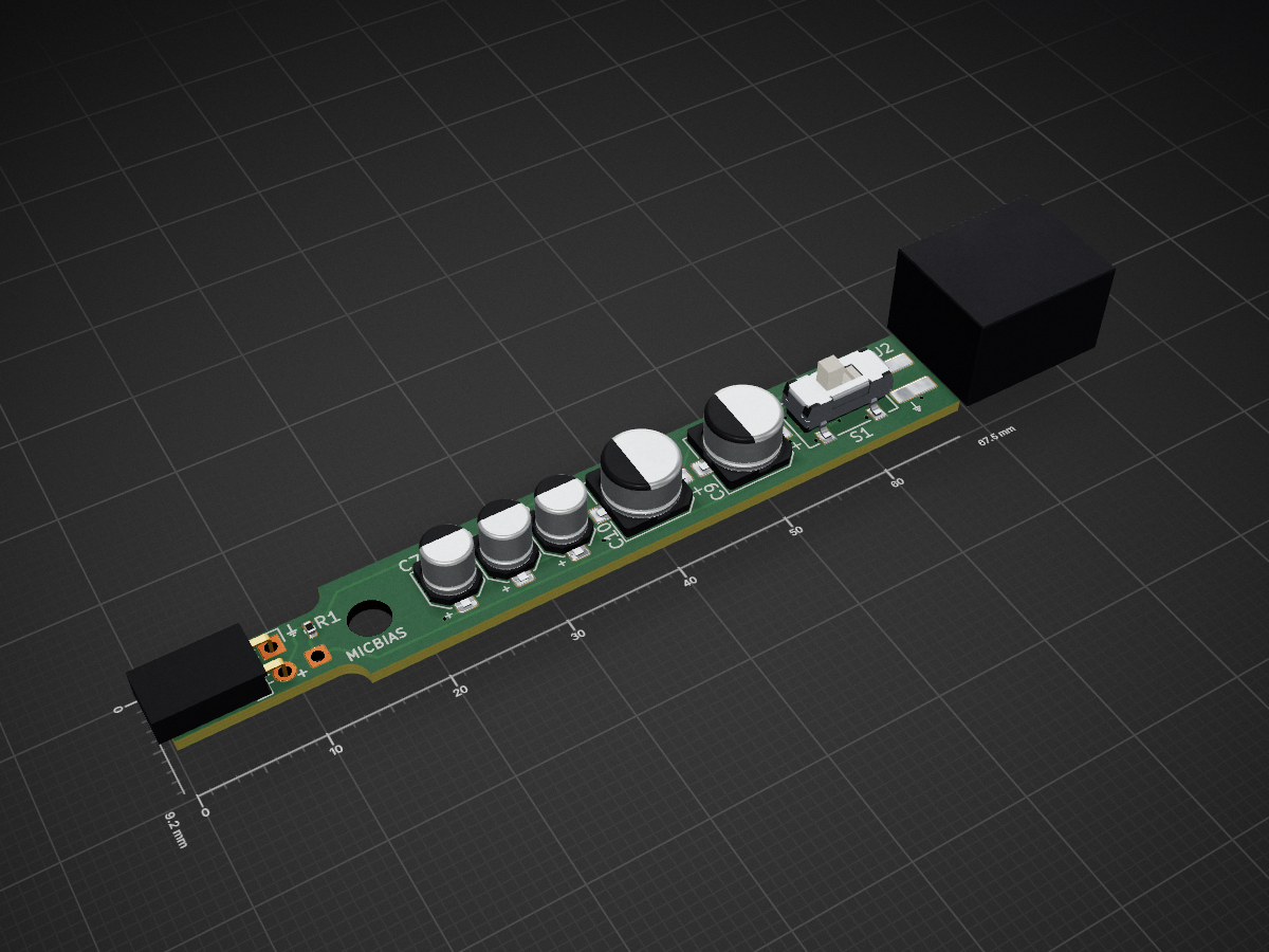
Ref mic is an open-source printed circuit board by loudifier, from the loudifier/OpenRefMic repository on GitHub, published under the MIT licence. It is a 4-layer board of 67.5 × 9.2 mm with 47 parts on 24 nets, routed with 261 tracks and 37 vias.
It is built around the OPA4991ID, AOM-5024L-HD-F-R and CL-SB-12B-01T. Its parts include 23 resistors, 15 capacitors, 4 diodes, 2 connectors and 1 IC. It belongs with the audio and music boards of this library.


OpenRefMic is an open hardware design for a reference microphone that fits in the popular 1/2" reference microphone form factor, works with consumer microphone interfaces, and meets or exceeds the performance of professional reference microphones at a vastly reduced total system cost.
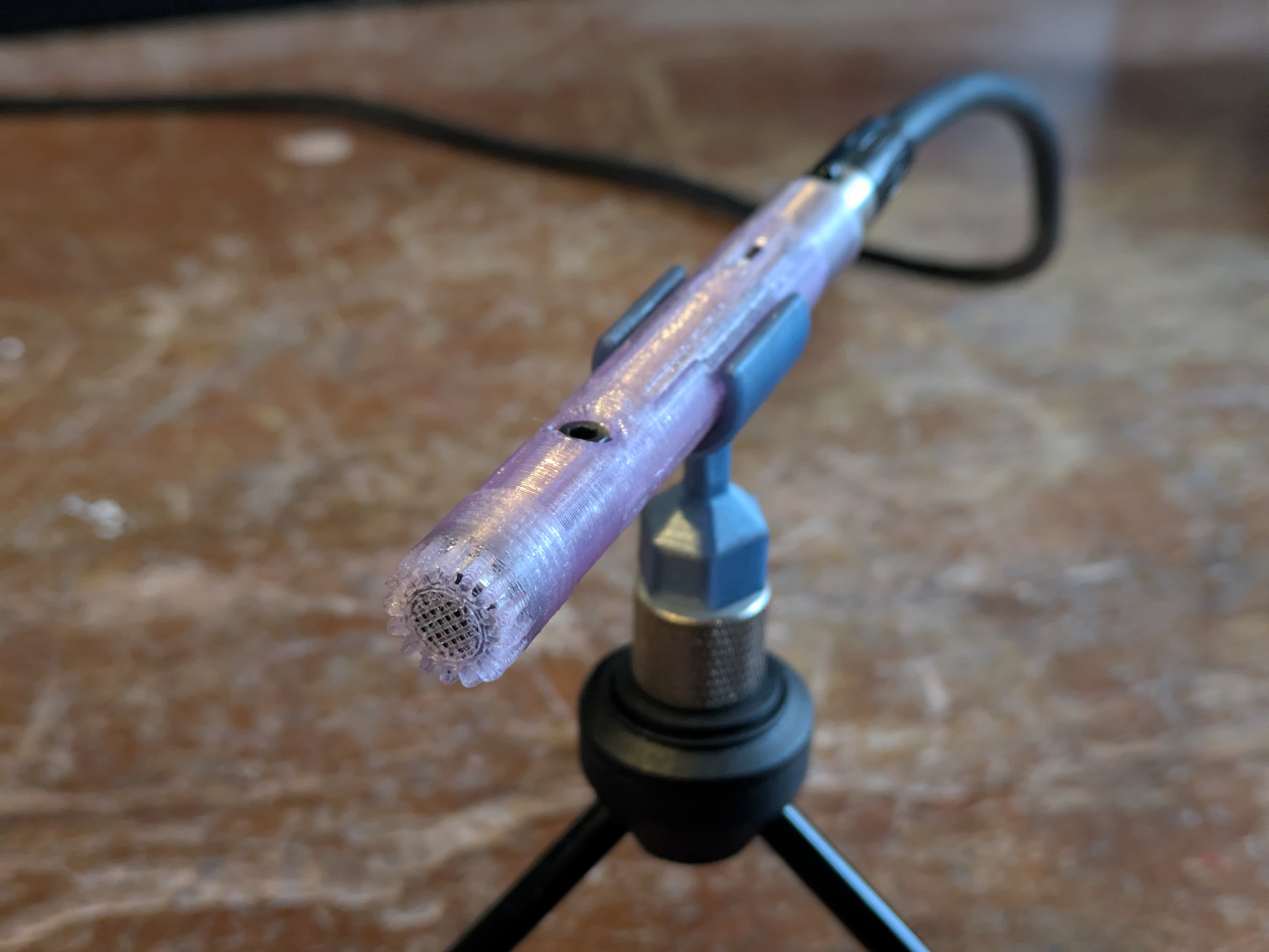
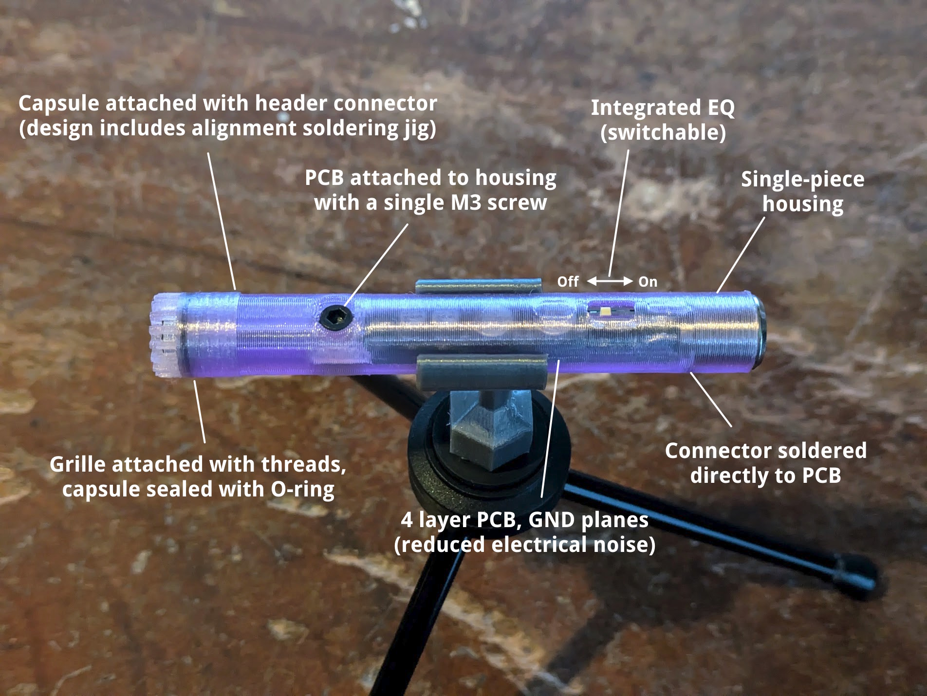
OpenRefMic version 2 significantly improves the usability of the mic, with integrated frequency response correction, improved PCB layout, and a simpler and more robust mechanical design.
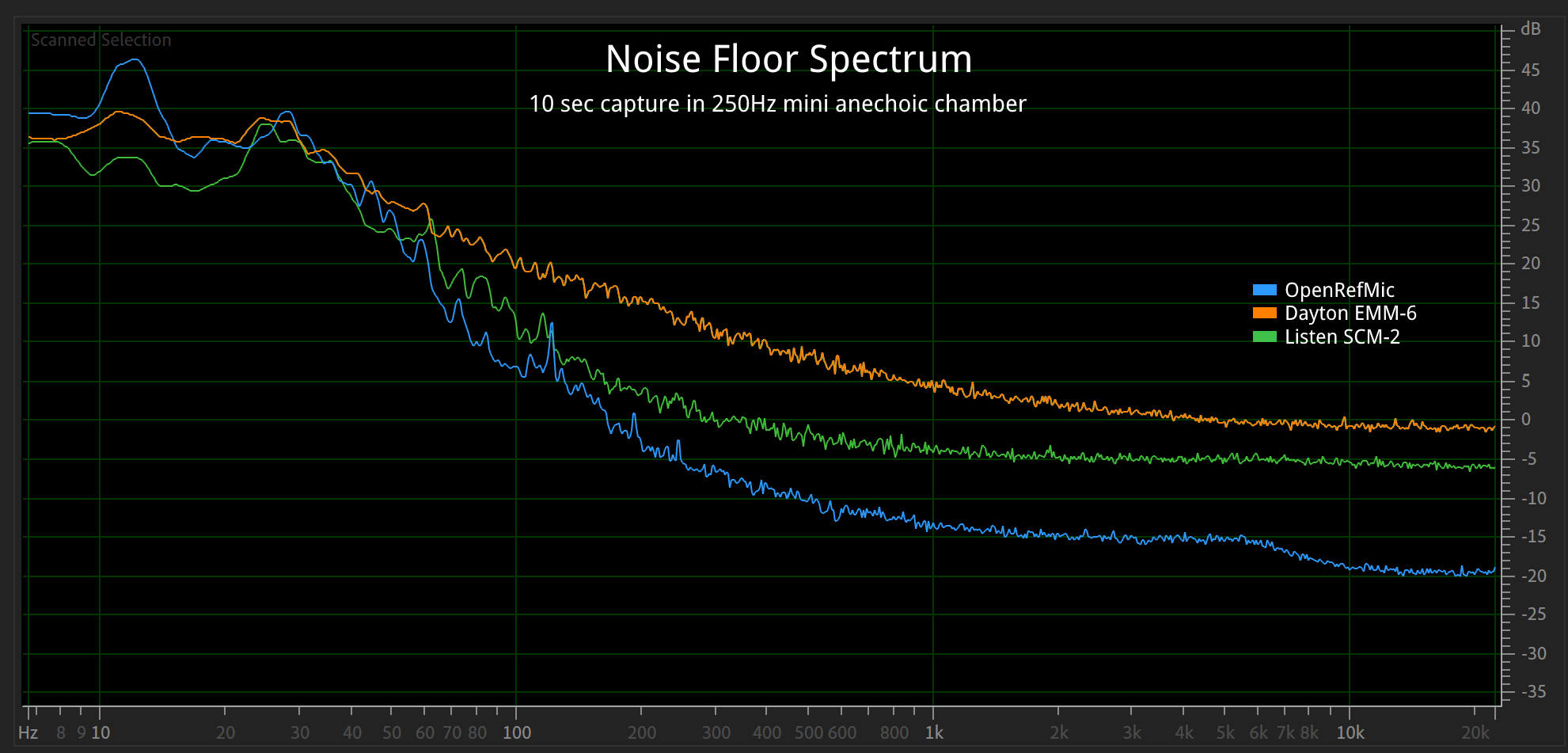
| Mic | Interface | Frequency Response (20-20k) | Noise Floor | AOP | Price |
|---|---|---|---|---|---|
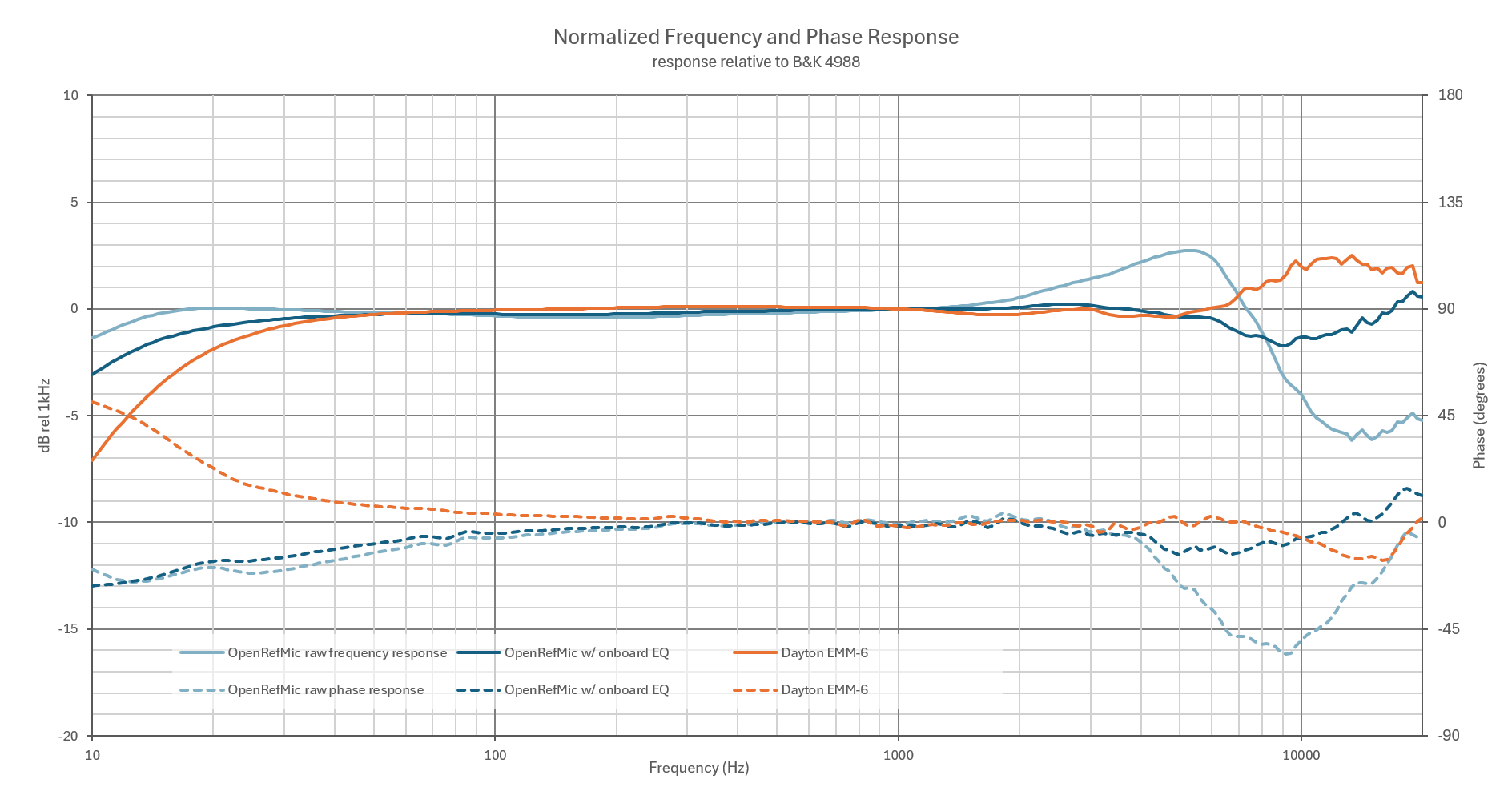
| OpenRefMic | 48V phantom power, mini XLR | +3/-7dB (±2dB with EQ) | 17dBA | 118dBSPL | Typically <$60 |
| Dayton EMM-6 | 15-48V phantom power, XLR | ±2dB | 36dBA | 127dBSPL | $60 |
| MiniDSP U-MIK 2 | USB-C | Not specified (likely ±2dB) | 20dBA | 125dBSPL | $195 + import |
| PCB 376A32 | 12-48V phantom power, XLR | ±2dB | 15.5dBA | 137dBSPL | $1,445 |
| B&K 4191 | 200V Lemo | <±1dB | 20dBA | 162dBSPL | Ask for price ($$$) |
| GRAS 46AE | CCP BNC | ±2dB | 17dBA | 138dBSPL | Ask for price ($$$) |
The core of the OpenRefMic design is a preamplifier that biases an electret microphone from 48V phantom power, buffers the microphone signal, applies a frequency response correction filter, and to sends the signal to a standard microphone interface. The circuit was designed for the PUI AOM-5024L-HD-F-R low noise microphone capsule, and has been built and tested with that part, but should work with most other electret mics. The schematic and PCB layout were designed in KiCAD and are available in the Preamplifier section of the project, along with the BOM for all electrical and mechanical parts.
OpenRefMic construction is simple, consisting of a 3D printed housing, the PCB, mic capsule, screw/nut, and optionally an O-ring and dab of UV cure glue. CAD in Fusion360 and STEP formats are in the Assembly section, along with STLs for the printed parts and a step-by-step construction guide.
The noise performance of the complete OpenRefMic prototype far exceeds that of comparably-priced measurement microphones, with a flat frequency response suitable as a reference microphone for measuring speakers, distortion, noise emissions, and capturing field recordings. Raw measurement data, compensation curves, and recommendations for applying calibrations to measurements and recordings are in the Calibration section.
This is the most important factor of the OpenRefMic project, and all of the other performance metrics and goals are considered "nice to have". While there are several popular affordable measurement microphones on the market (like the Dayton EMM-6), their noise performance ranges from mediocre to poor. Even professional reference microphones tend to prioritize frequency response flatness over noise performance, and very low noise reference microphones are prohibitively expensive for the hobbyist or self-funded experimenter. The video below is an example of the dramatic difference in noise performance between OpenRefMic and the Dayton EMM-6.
field recording noise comparison
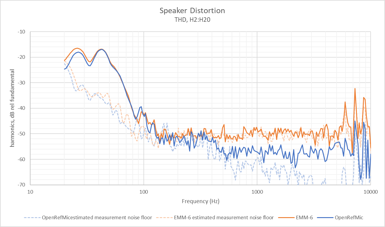
Low noise is obviously helpful for applications like field recordings or measuring low-level noise emissions, but one area where microphone noise floor is often overlooked is in speaker distortion measurements. Increasing the stimulus and analysis window or moving the microphone closer to the speaker can help resolve lower distortion levels, but those options may not always be feasible for the given speaker or test setup. The graph below is an example of the differences that you might see between distortion measurements with a typical budget measurement mic with a ~34dBA noise floor and an OpenRefMic with ~18dBA noise floor.
A reference microphone should have a frequency response that is flat or characterized well enough that it can be understood how measurements and recordings relate to absolute physical constants. Some aberrations in the off-axis response is expected, particularly at very high frequencies, but the design of the housing, porting, and front grille should minimize directional effects as much as possible. In cases where a flat frequency response is not achievable, the response should be characterized and a process should be defined to apply reciprocal filters to correct recordings.
The microphone element in OpenRefMic has a very low noise floor, but it does not have a flat frequency response. See the calibration page for a compensation curve and filter settings to correct measurements and recordings.
Professional reference microphones typically require interfaces that are uncommon outside of labratory settings. IEPE current loops over BNC cables on the more affordable end of the spectrum and 200V polarization supplied via LEMO connectors at the other end, where the cable itself is often over $500. The pro audio world has instead standardized on balanced signals and phantom powering over cheap XLR cables, and OpenRefMic is designed to achieve high performance with these affordable interfaces.
Compatibility with consumer-grade microphone interfaces eliminates the prohibitive costs of an IEPE or LEMO interface, but the parts availability and BOM cost of the microphone itself should be comparable to that of measurement microphones that target the DIY speaker building market. The parts needed to build an OpenRefMic are cheap and, with the low prices of desktop 3D printers and PCB fabrication services, many builders will be able to make their own OpenRefMic for less than they would spend on a budget measurement microphone.
Many measurement microphones fit a 1/2" cylindrical form factor, or at least have a long probe end with a 1/2" diameter, which helps maintain omnidirectional frequency response up to several kilohertz. Phantom powering necessitates relatively large capacitors, but the OpenRefMic PCB just barely fits within a 1/2" cross-section. Using a mini-XLR connector, the overall microphone dimensions are 12.7x92mm, almost identical to a reference microphone from B&K or GRAS.
Note that the front grille diameter for OpenRefMic v2 is 13.2mm, which is the de facto standard for professional reference microphones. The slightly increased diameter allows enough space to include an O-ring to seal the mic capsule, threads to actually attach the grille to the mic body, and is wide enough to properly seal to a standard 1/2" pistonphone calibrator.
Specialized shapes for specific applications are left up to individual builders, but please share your design if you would like to add additional form factors to the project.
| Qty | Value | Footprint | References |
|---|---|---|---|
| 5 | 22uF 16V | OpenRefMic:C_1210_3225Metric_0.95mm-height | C11, C12, C13, C14, C15 |
| 5 | 7.15k | Resistor_SMD:R_0402_1005Metric | R11, R18, R19, R20, R21 |
| 4 | 10nF | Capacitor_SMD:C_0402_1005Metric | C3, C4, C5, C6 |
| 3 | 0 | Resistor_SMD:R_0402_1005Metric | R9, R14, R15 |
| 3 | 10uF 16V | Capacitor_SMD:CP_Elec_4x4.5 | C1, C2, C7 |
| 2 | 100R | Resistor_SMD:R_0402_1005Metric | R16, R17 |
| 2 | 10k | Resistor_SMD:R_0402_1005Metric | R10, R13 |
| 2 | 1N4148 | Diode_SMD:D_SOD-523 | D1, D4 |
| 2 | 22uF 25v | Capacitor_SMD:CP_Elec_6.3x4.5 | C9, C10 |
| 2 | 33k | Resistor_SMD:R_0402_1005Metric | R22, R23 |
| 2 | 4.7k | Resistor_SMD:R_0402_1005Metric | R1, R8 |
| 1 | 0.1uF | Capacitor_SMD:C_0402_1005Metric | C8 |
| 1 | 1.74k | Resistor_SMD:R_0402_1005Metric | R3 |
| 1 | 100k | Resistor_SMD:R_0402_1005Metric | R7 |
| 1 | 2.67k | Resistor_SMD:R_0402_1005Metric | R4 |
| 1 | 2.94k | Resistor_SMD:R_0402_1005Metric | R2 |
| 1 | 24V | Diode_SMD:D_SOD-523 | D2 |
| 1 | 5.6V | Diode_SMD:D_SOD-523 | D3 |
| 1 | 75k | Resistor_SMD:R_0402_1005Metric | R12 |
| 1 | 8.06k | Resistor_SMD:R_0402_1005Metric | R6 |
| 1 | 825R | Resistor_SMD:R_0402_1005Metric | R5 |
| 1 | AOM-5024L-HD-F-R | Connector_PinSocket_2.54mm:PinSocket_1x02_P2.54mm_Horizontal | MK1 |
| 1 | CL-SB-12B-01T | OpenRefMic:CL-SB-12B-01_NDC | S1 |
| 1 | MEMS micbias | Connector_Wire:SolderWire-0.1sqmm_1x01_D0.4mm_OD1mm | J1 |
| 1 | Mini XLR Male | OpenRefMic:Switchcraft_T3BM_edgemount | J2 |
| 1 | OPA4991 | Package_SO:SO-14_3.9x8.65mm_P1.27mm | U1 |
It measures 67.5 × 9.2 mm and has 4 copper layers, 1.14 mm thick.
47 parts, built around the OPA4991ID, AOM-5024L-HD-F-R and CL-SB-12B-01T. The full list of its parts is on this page, with links to each part's symbol and footprint where PCBKit's library has them.
From the loudifier/OpenRefMic repository on GitHub, at the commit this page was made from: the board is preamplifier/ref_mic/ref_mic.kicad_pcb and its schematic preamplifier/ref_mic/ref_mic.kicad_sch. PCBKit opens the board in the browser, with nothing to install.
Its repository publishes it under the MIT licence: you may reuse it on that licence's terms (keep the author's notice, and for a copyleft licence share your changes alike).

Haimana/MAIANA_BLUE
Firmware and hardware materials for the MAIANA-class AIS transponder ecosystem. The design builds on the open MAIANA project (GPL v3, Peter Antypas).

ad4363/LuX-ray-PCBs
A repository containing KiCad schematic and pcb files for a wireless radiation detector testing interface

rolandvs/ais_transponder
A real, functioning low-power AIS transponder (class B)


wntrblm/Helium
Helium is a triple 1-to-3 precision buffered multiple and 3-to-1 precision adder

