6 layers133.1 × 133.1 mm
AERIS H743-PCB
7903555032/AERIS-H743-PCB
A 6-layer STM32H743-based embedded development and flight-control/data-logging PCB designed as a practical hardware-design and PCB-layout project.
114 parts1
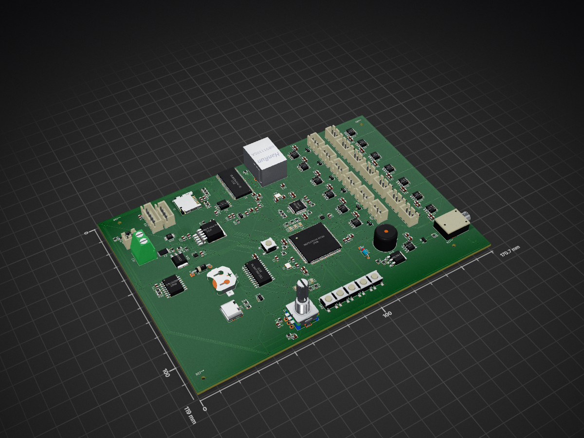
 llextv/coreLight
CoreLight is an open-source DIY lighting controller built around an STM32H743.
CoreLight is an open-source printed circuit board by llextv, from the llextv/coreLight repository on GitHub. It is a 4-layer board of 170.7 × 119 mm with 196 parts on 255 nets, routed with 4,498 tracks and 840 vias.
It is built around the MAX3485ED, W25Q128JVSIQ and AP2112K-3.3, with the CD74HC4067M, DS3231MZ+ and USBLC6-2SC6 among its other parts. Its parts include 67 capacitors, 38 resistors, 26 ICs, 23 diodes and 21 connectors.


CoreLight is an open-source DIY lighting controller built around an STM32H743.
The project is designed to manage stage lighting systems with up to 13 DMX universes, Ethernet protocols such as Art-Net and sACN, timecode synchronization, show playback and system monitoring.
The goal is not to recreate a grandMA3 console. CoreLight is intended to be a hardware platform for a future open-source lighting-control system.
Most of these features are still under development. The current version should be considered a hardware prototype rather than a finished lighting controller.
The STM32H743 is the central processor of the system. It handles network communication, timecode, DMX processing, show playback and system monitoring.
The controller can also receive LTC, MTC and external event inputs. Lighting data is processed by the STM32 and sent to the required DMX outputs.
The current design uses the following main components:
| Component | Function |
|---|---|
| STM32H743ZIT6 | Main microcontroller |
| W5500 | Ethernet interface |
| MAX3485 | DMX / RS-485 transceivers |
| CD74HC4067M | Signal routing and multiplexing |
| IS42S16400J-7TL | External SDRAM |
| W25Q128JVSIQ | SPI Flash |
| DS3231M+ | Real-time clock |
| INA226AIDGST | Power monitoring |
| TMP117AIDRVR | Temperature monitoring |
| SM712 | DMX transient protection |
| USBLC6-2SC6 | USB ESD protection |
The complete component list is available in BOM.csv.
The STM32H743 was selected because the project requires more processing power and memory bandwidth than a basic microcontroller-based DMX interface.
It is responsible for:
The external SDRAM is used for temporary runtime data such as:
The W25Q128JVSIQ Flash can be used for firmware, configuration and persistent system data.
The microSD card is intended for user-accessible files:
/show
/config
/logs
/firmware
Shows, configuration files, logs and firmware updates can be stored on the card.
CoreLight is designed to support up to 13 DMX universes.
Each output uses a MAX3485 RS-485 transceiver and includes transient protection. A DMX universe contains up to 512 channels, giving a theoretical total of:
[ 13 \times 512 = 6656 \text{ DMX channels} ]
Standard DMX wiring is used
The DMX data rate is 250 kbit/s.
Planned DMX features include:
For example, one network universe could be sent to several physical outputs
Ethernet communication is handled by the W5500.
The network interface is intended to support:
Network universes can be mapped to any of the physical DMX outputs instead of being permanently assigned to a single port.
CoreLight includes an LTC input and is designed to support MTC.
Timecode can be used to trigger lighting events or control show playback:
Example events could include scene changes, effect triggers or the start of a complete lighting sequence.
The RTC is used for system time, logs and scheduled events. It is separate from LTC, which is used for show synchronization.
A show can be uploaded to the microSD card and played back without a permanent computer connection.
A show file may contain:
During playback, the STM32 loads the required data and generates the DMX output in real time.
One of the main objectives is to improve system reliability during shows.
CoreLight is intended to detect problems such as:
Depending on the final firmware, the controller could switch to a backup source or continue playback using a locally stored show.
DMX merging is also planned, allowing several sources to contribute to the same output:
The merging rules and failover behavior are still being designed.
The system includes temperature and power monitoring using a TMP117 and an INA226.
The firmware will be able to control the cooling fan and warn the user in case of excessive temperature or abnormal power consumption.
Available hardware includes:
The controller is designed for a 24 V DC input.
The regulated voltages power the STM32, Ethernet interface, DMX transceivers, sensors and other logic circuits.
The initial local interface consists of:
A future web interface will provide access to:
The controller is intended to be configurable from a browser without requiring a dedicated screen.
Software link for the moment: https://www.qlcplus.org/download#
The PCB was designed in KiCad and uses four layers to simplify routing and provide dedicated ground and power planes.
The board contains:
The current design contains approximately 192 footprints.
The enclosure is a custom 3D-printed rack-mount case with openings for the DMX outputs, Ethernet, USB-C, LTC, power, fan and user controls.
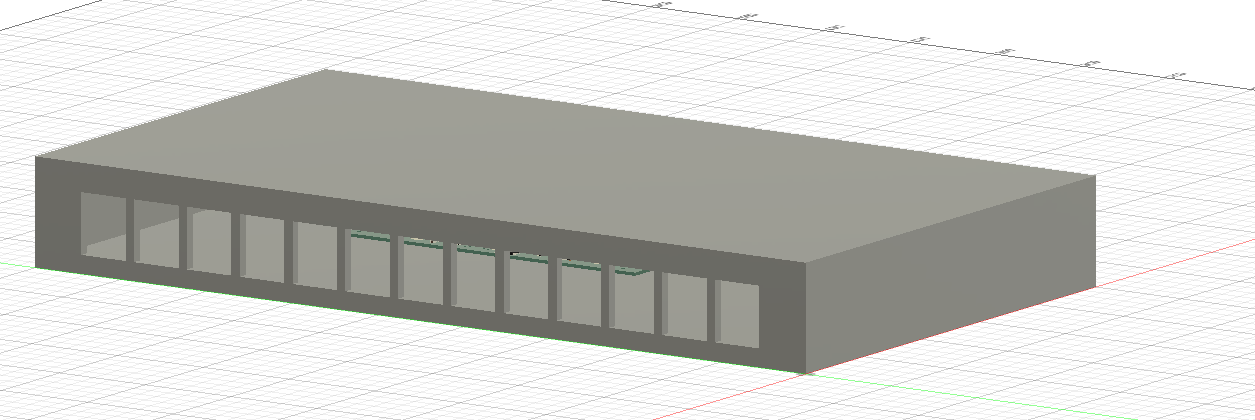
Assembly file: coreLightAssembly.step
CAD files are available in:
/cadThe complete KiCad schematic is available in:
/scheme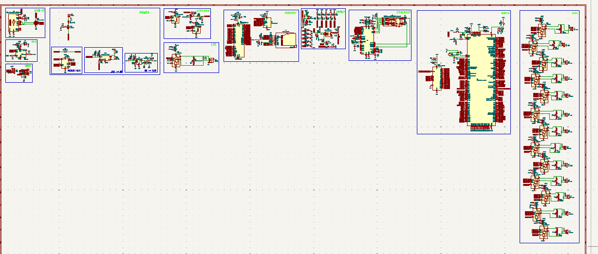
The current estimate is:
Components:  $66.01
PCB:         $36.99
Total:      ~$103 USD
This does not include shipping, assembly, enclosure parts or future design changes.
The development process is documented in JOURNAL.md.
It includes the PCB design, STM32CubeMX configuration, KiCad work, enclosure design, BOM creation and the problems encountered during development.
CoreLight was inspired by professional lighting hardware such as the grandMA3 Processing Unit and Replay Unit.
The project is independent and is not affiliated with MA Lighting.
| Qty | Value | Footprint | References |
|---|---|---|---|
| 33 | 100nF | Capacitor_SMD:C_0805_2012Metric | C1, C4, C13, C16, C27, C29, C30, C31, C34, C36, C39, C42, C44, C46, C48, C50 +17 |
| 21 | 4.7µF | Capacitor_SMD:C_0805_2012Metric | C5, C28, C35, C40, C41, C43, C45, C47, C49, C51, C53, C55, C57, C59, C61, C63 +5 |
| 15 | 10k | Resistor_SMD:R_0805_2012Metric | R1, R4, R5, R6, R9, R42, R58, R74, R80, R82, R83, R84, R88, R89, R90 |
| 14 | MAX3485 | Package_SO:SOIC-8_3.9x4.9mm_P1.27mm | U6, U7, U8, U9, U10, U11, U12, U13, U14, U15, U16, U17, U18, U27 |
| 13 | Con DMX | Connector_JST:JST_XH_B3B-XH-A_1x03_P2.50mm_Vertical | J5, J6, J21, J23, J24, J25, J26, J27, J28, J29, J30, J31, J32 |
| 13 | SM712 | PCM_JLCPCB:D_SOT-23 | D31, D33, D34, D35, D36, D37, D38, D39, D40, D41, D42, D43, D44 |
| 9 | 330R | Resistor_SMD:R_0805_2012Metric | R2, R3, R10, R11, R12, R13, R14, R15, R16 |
| 7 | LED | LED_SMD:LED_0805_2012Metric | D47, D48, D49, D50, D51, D52, D53 |
| 5 | 100k | Resistor_SMD:R_0805_2012Metric | R59, R72, R75, R85, R86 |
| 5 | SW_Push | Button_Switch_SMD:SW_Push_1P1T_NO_6x6mm_H9.5mm | SW3, SW4, SW5, SW6, SW7 |
| 4 | 22pF | Capacitor_SMD:C_0805_2012Metric | C2, C3, C32, C33 |
| 2 | 10nF | Capacitor_SMD:C_0805_2012Metric | C73, C74 |
| 2 | 10uF | Capacitor_SMD:C_0805_2012Metric | C26, C70 |
| 2 | 1uF | Capacitor_SMD:C_0805_2012Metric | C12, C81 |
| 2 | 4.7uF | Capacitor_SMD:C_0805_2012Metric | C37, C67 |
| 2 | 5.1K | Resistor_SMD:R_0805_2012Metric | R43, R44 |
| 2 | Crystal 25MHz | Crystal:Crystal_SMD_3225-4Pin_3.2x2.5mm | Y1, Y3 |
| 2 | FerriteBead | Capacitor_SMD:C_0805_2012Metric | FB1, FB3 |
| 2 | MOSFET | Package_TO_SOT_SMD:TO-252-3_TabPin2 | Q14, Q16 |
| 2 | TMP117xxDRV | Package_SON:WSON-6-1EP_2x2mm_P0.65mm_EP1x1.6mm | U23, U24 |
| 1 | 10-50mΩ | Resistor_SMD:R_0805_2012Metric | R45 |
| 1 | 100R | Resistor_SMD:R_0805_2012Metric | R76 |
| 1 | 12.1k | Resistor_SMD:R_0805_2012Metric | R7 |
| 1 | 12.4k | Resistor_SMD:R_0805_2012Metric | R8 |
| 1 | 120R | Resistor_SMD:R_0805_2012Metric | R87 |
| 1 | 1N4148 | Diode_THT:D_DO-35_SOD27_P7.62mm_Horizontal | D32 |
| 1 | 1N5819 | Diode_THT:D_DO-41_SOD81_P10.16mm_Horizontal | D17 |
| 1 | 1k | Resistor_SMD:R_0805_2012Metric | R41 |
| 1 | 2.2nF | Capacitor_SMD:C_0805_2012Metric | C80 |
| 1 | 24v in | TerminalBlock_Phoenix:TerminalBlock_Phoenix_MKDS-1,5-2-5.08_1x02_P5.08mm_Horizontal | J17 |
| 1 | 2N7002/AOD | PCM_JLCPCB:Q_SOT-23 | Q15 |
| 1 | 52.3k | Resistor_SMD:R_0805_2012Metric | R73 |
| 1 | AP2112K-3.3 | Package_TO_SOT_SMD:SOT-23-5 | U21 |
| 1 | BOOT | Button_Switch_SMD:SW_Push_1P1T_NO_6x6mm_H9.5mm | SW1 |
| 1 | Battery | Battery:BatteryHolder_Keystone_3000_1x12mm | BT1 |
| 1 | Buzzer 3.3V | Buzzer_Beeper:Buzzer_12x9.5RM7.6 | BZ1 |
| 1 | CD74HC4067M | Package_SO:SOIC-24W_7.5x15.4mm_P1.27mm | U25 |
| 1 | DS3231M | Package_SO:SOIC-16W_7.5x10.3mm_P1.27mm | U19 |
| 1 | D_TVS_Dual_AAC | PCM_JLCPCB:D_SOT-23 | D4 |
| 1 | EC11 with BTN | Rotary_Encoder:RotaryEncoder_Alps_EC11E-Switch_Vertical_H20mm | SW2 |
| 1 | FAN | Connector_JST:JST_XH_B2B-XH-A_1x02_P2.50mm_Vertical | J18 |
| 1 | Fuse 3-5A | Fuse:Fuse_1812_4532Metric_Pad1.30x3.40mm_HandSolder | F2 |
| 1 | INA226 | Package_SO:VSSOP-10_3x3mm_P0.5mm | U22 |
| 1 | IS42S16400J-xC | Package_SO:TSOP-II-54_22.2x10.16mm_P0.8mm | U2 |
| 1 | LM2596S-ADJ 5V | Package_TO_SOT_SMD:TO-263-5_TabPin3 | U20 |
| 1 | LTC IN | Connector_Audio:Jack_3.5mm_Ledino_KB3SPRS_Horizontal | J22 |
| 1 | Micro_SD_Card | Connector_Card:microSD_HC_Hirose_DM3D-SF | J1 |
| 1 | NUCLEO144-H743ZI | Package_QFP:LQFP-144-1EP_20x20mm_P0.5mm_EP6.5x6.5mm | U4 |
| 1 | RJ45_Hanrun_HR911105A_Horizontal | Connector_RJ:RJ45_Hanrun_HR911105A_Horizontal | J3 |
| 1 | SWD | Connector_JST:JST_XH_B5B-XH-A_1x05_P2.50mm_Vertical | J19 |
| 1 | UART | Connector_JST:JST_XH_B4B-XH-A_1x04_P2.50mm_Vertical | J20 |
| 1 | USBLC6-2SC6 | Package_TO_SOT_SMD:SOT-23-6 | U26 |
| 1 | USB_C_Receptacle_USB2.0_16P | Connector_USB:USB_C_Receptacle_HRO_TYPE-C-31-M-12 | J16 |
| 1 | W25Q128JVS | Package_SO:SOIC-8_5.23x5.23mm_P1.27mm | U3 |
| 1 | W5500 | Package_QFP:LQFP-48_7x7mm_P0.5mm | U5 |
The 192 most common of 196 parts.
It measures 170.7 × 119 mm and has 4 copper layers, 1.6 mm thick.
196 parts, built around the MAX3485ED, W25Q128JVSIQ, AP2112K-3.3 and CD74HC4067M. The full list of its parts is on this page, with links to each part's symbol and footprint where PCBKit's library has them.
From the llextv/coreLight repository on GitHub, at the commit this page was made from: the board is scheme/coreLight.kicad_pcb and its schematic scheme/coreLight.kicad_sch. PCBKit opens the board in the browser, with nothing to install.
Its repository states no licence, so its author keeps all rights: ask llextv before reusing the design.
7903555032/AERIS-H743-PCB
A 6-layer STM32H743-based embedded development and flight-control/data-logging PCB designed as a practical hardware-design and PCB-layout project.

Markus4771/Fenstersteuerung
Dieser Ordner enthält historische KiCad-PCB-Zwischenstände der Hauptplatine.

tombueng/LuxDMX
Open-source Art-Net / sACN (E1.31) → DMX512 gateway for ESP32 / ESP32-S3 / Ethernet. Live web UI shows all 512 channels in real time, flags console conflicts, and drives galvanically-isolated DMX.

beleata/fpga-led-panel-sram
iCE40HX1K 64x32 ICND1065L RGB panel with double-buffered SRAM and 2 Mbaud UART image upload

Stab-Rabbit-coding/Serenity-UAV
A functional, security conscious, Unmanned Aerial Vehicle based on the Firefly Class spacecraft Serenity from the 2002 show..


