2 layers16.8 × 36 mm
 LizOnAir/Camera
A Camera with customize pcb.
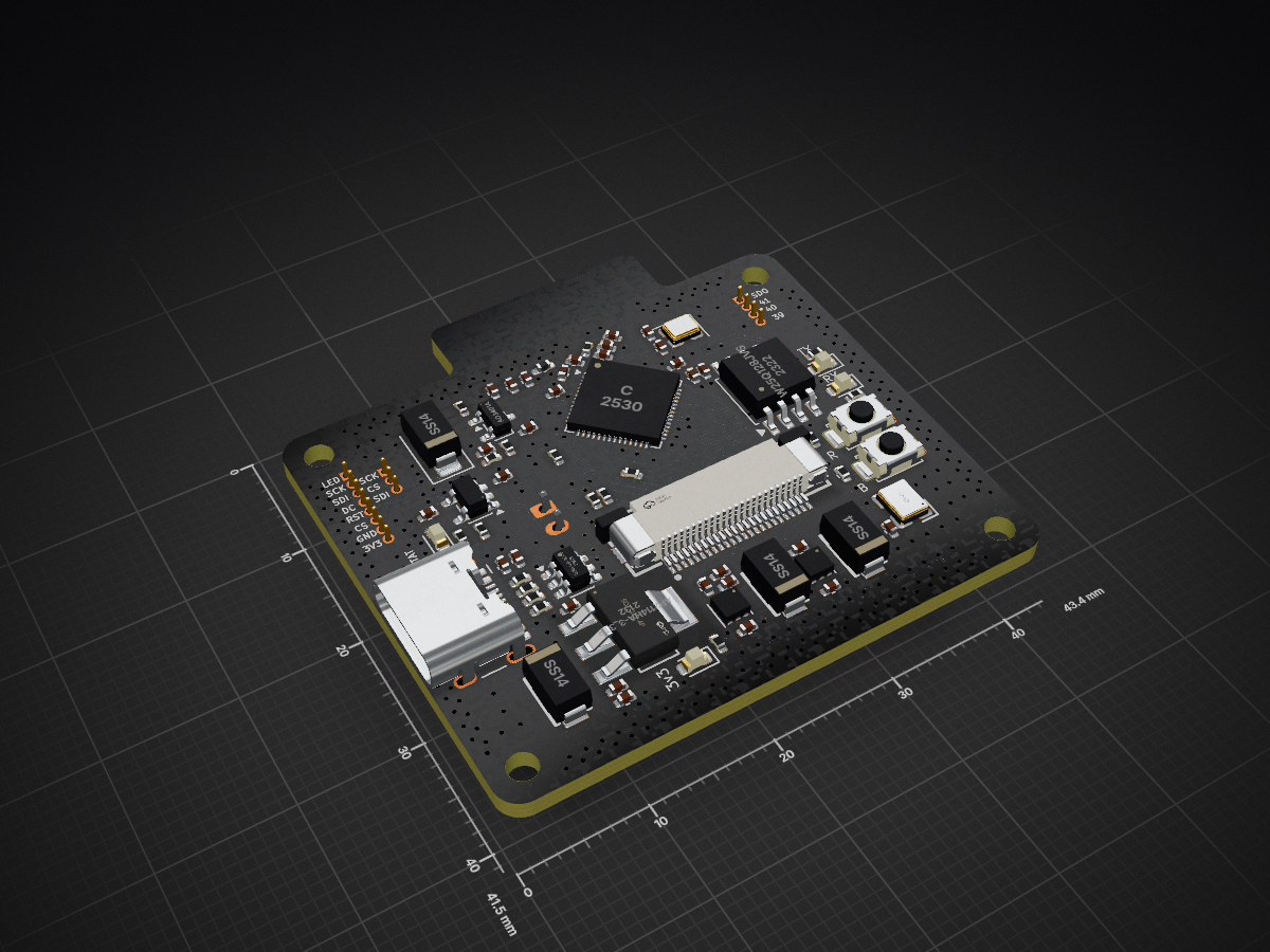
Devboard is an open-source printed circuit board by LizOnAir, from the LizOnAir/Camera repository on GitHub. It is a 4-layer board of 43.4 × 41.5 mm with 81 parts on 78 nets, routed with 930 tracks and 395 vias.
It is built around the W25Q128JVSIQ, TLV75515PDRV and TLV75518PDRV, with the USBLC6-2SC6, SS14 and 3N24000G33YC among its other parts. Its parts include 30 capacitors, 18 resistors, 8 diodes, 7 ICs and 6 connectors. It belongs with the microcontroller boards boards of this library.


This camera consist of a custom PCB and buttons as well as a 2.4 inch tft display with sd card slot, that can capture picture. I made this project to improve my knowledge about PCB design and also I personally really wanna make a retro camera with noisy resolution. Through this project, I learnt about high speed signals, parallel signals and heat management.
Made in Fusion360.Liz Access files in CAD folder.
Steps:
Here's my PCB! It was made in KiCad.
Main board
Camera - OV5640
Access files in PCB folder.
I use Arduino IDE to program this camera
Access files in Firmware folder.
Here should be everything you need to make this:
| Qty | Value | Footprint | References |
|---|---|---|---|
| 10 | 0.1uF | Capacitor_SMD:C_0402_1005Metric | C1, C2, C8, C12, C13, C14, C17, C20, C33, C34 |
| 7 | 1uF | Capacitor_SMD:C_0402_1005Metric | C3, C7, C18, C21, C27, C28, C30 |
| 5 | 10UF | Capacitor_SMD:C_0402_1005Metric | C4, C5, C10, C11, C26 |
| 4 | 1k | PCM_JLCPCB:R_0402 | R3, R10, R21, R22 |
| 4 | LED | LED_SMD:LED_0603_1608Metric | D1, D3, D4, D6 |
| 3 | 470 | PCM_JLCPCB:R_0402 | R7, R8, R9 |
| 3 | SS14 | JLCImport:SS14 | D5, D7, D8 |
| 2 | 0 | PCM_JLCPCB:R_0402 | R5, R11 |
| 2 | 10k | Resistor_SMD:R_0402_1005Metric | R4, R6 |
| 2 | 10nF | Capacitor_SMD:C_0402_1005Metric | C6, C19 |
| 2 | 200k | PCM_JLCPCB:R_0402 | R19, R20 |
| 2 | 22pF | Capacitor_SMD:C_0402_1005Metric | C22, C23 |
| 2 | 33 | PCM_JLCPCB:R_0402 | R14, R15 |
| 2 | 3pF | Capacitor_SMD:C_0402_1005Metric | C9, C15 |
| 2 | 4.7UF | Capacitor_SMD:C_0402_1005Metric | C31, C32 |
| 2 | 5.1k | PCM_JLCPCB:R_0402 | R1, R2 |
| 1 | 100k | PCM_JLCPCB:R_0402 | R18 |
| 1 | 2.4nH | PCM_JLCPCB:L_0402 | L2 |
| 1 | 2nH | Inductor_SMD:L_0402_1005Metric_Pad0.77x0.64mm_HandSolder | L1 |
| 1 | 3N24000G33YC | PCM_JLCPCB:OSC-SMD_4P-L3.2-W2.5-BL | X2 |
| 1 | 40MHz(10ppm) | Crystal:Crystal_SMD_2520-4Pin_2.5x2.0mm | Y1 |
| 1 | AO3401A | Package_TO_SOT_SMD:SOT-23 | Q1 |
| 1 | AP2114HA-3_3TRG1 | JLCImport:AP2114HA-3_3TRG1 | U8 |
| 1 | Antenna_Chip | RF_Antenna:Texas_SWRA117D_2.4GHz_Left | AE1 |
| 1 | Conn_01x03_Pin | Connector_PinHeader_1.00mm:PinHeader_1x03_P1.00mm_Vertical | J4 |
| 1 | Conn_01x04_Pin | Connector_PinHeader_1.00mm:PinHeader_1x04_P1.00mm_Vertical | J5 |
| 1 | Conn_01x08_Pin | Connector_PinHeader_1.00mm:PinHeader_1x08_P1.00mm_Vertical | J3 |
| 1 | Flash | PCM_JLCPCB:SW_TS-1088-AR02016 | Flash1 |
| 1 | MCP73831T-2DCI/OT | Package_TO_SOT_SMD:SOT-23-5 | U3 |
| 1 | PH-2AK | Connector_JST:JST_PH_S2B-PH-K_1x02_P2.00mm_Horizontal | CN2 |
| 1 | Reset | PCM_JLCPCB:SW_TS-1088-AR02016 | Reset1 |
| 1 | SS14 | Diode_SMD:D_SMA | D2 |
| 1 | TLV75515PDRV | Package_SON:WSON-6-1EP_2x2mm_P0.65mm_EP1x1.6mm | U5 |
| 1 | TLV75518PDRV | Package_SON:WSON-6-1EP_2x2mm_P0.65mm_EP1x1.6mm | U6 |
| 1 | USBLC6-2SC6 | Package_TO_SOT_SMD:SOT-23-6 | U7 |
| 1 | USB_C_Receptacle_USB2.0_14P | Connector_USB:USB_C_Receptacle_HCTL_HC-TYPE-C-16P-01A | J1 |
| 1 | W25Q128JVS | Package_SO:SOIC-8_5.3x5.3mm_P1.27mm | U4 |
| 1 | c | Package_DFN_QFN:QFN-56-1EP_7x7mm_P0.4mm_EP4x4mm | U1 |
| 1 | ~ | Connector_FFC-FPC:FPC-SMD_KH-FG0.5-H2.0-24PIN | CN1 |
The 77 most common of 81 parts.
It measures 43.4 × 41.5 mm and has 4 copper layers, 1.6 mm thick.
81 parts, built around the W25Q128JVSIQ, TLV75515PDRV, TLV75518PDRV and USBLC6-2SC6. The full list of its parts is on this page, with links to each part's symbol and footprint where PCBKit's library has them.
From the LizOnAir/Camera repository on GitHub, at the commit this page was made from: the board is PCB/PCB board/Devboard.kicad_pcb and its schematic PCB/Schematic/Button.kicad_sch. PCBKit opens the board in the browser, with nothing to install.
Its repository states no licence, so its author keeps all rights: ask LizOnAir before reusing the design.


openconcepts-ar/accel2d
This project aims to provide a graphics server system based on hardware accelerated graphics, and a easy way to develop the graphics primitives.

ZharbolatDinmukhamed/Haptic-Glove-PCB
A wrist-mounted PCB for a haptic feedback glove, developed as part of my Research Assistantship at the Tactile Laboratory, Nazarbayev University.

dosdude1/2.5-inch-ide-ssd
A custom-designed IDE SSD for use in any machine that utilizies a 2.5" IDE hard disk.


dosdude1/zif-ide-ssd
A custom-designed IDE SSD for use in any machine that utilizies a 1.8" ZIF IDE hard disk.

