2 layers213.4 × 130.8 mm
Issue 4
iansbremner/ZX-Spectrum-Issue-4B-KiCAD
Recreation of the ZX Spectrum Issue 4B board in KiCAD
199 parts22

 liveboxandy/ZX-Spectrum-48K-Issue-23
KiCAD created files for the ZX Spectrum 48K Issue 2 designed by Sinclair Research Ltd
ZX Spectrum i2 is an open-source printed circuit board by liveboxandy, from the liveboxandy/ZX-Spectrum-48K-Issue-2 repository on GitHub, published under the CC0-1.0 licence. It is a 2-layer board of 213.1 × 130 mm with 199 parts on 170 nets, routed with 6,203 tracks and 449 vias.
It is built around the 74LS157PC, 74LS00SC and 74LS32SC, with the L7805 among its other parts. Its parts include 73 resistors, 51 capacitors, 28 ICs, 15 diodes and 4 connectors. It belongs with the retro computing and games boards of this library.


This is a Kicad 10 project for an issue 2 16/48K ZX spectrum.
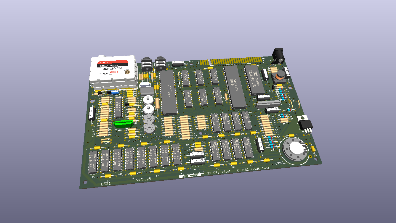
It was only done in order to produce an interactive bom (ibom.html) in the bom folder to aid in the debugging of faulty Speccies.
Although the gerbers appear to be correct to the original PCB I would not use them to get a PCB manufactured without a lot of checking.
It was created by overlaying pictures of a raw Issue 2 PCB, topside and bottomside and then creating the pcb layout from those and a readily available schematic.
Where there are differences the pictures took priority for routing and connections.
Where possible the Sinclair routing has been followed, including all the ground planes.
Various mods have been released and the following have been applied to the pcb and schematic layout,
D14 replaced by C67 (100pF) - Machine Code fix
R24 changed from 3K3 to (1K) - Machine Code fix
R27 changed from 680R to (470R) - Machine Code fix
R73 added between IC1/32 and +5V (1K) - Machine Code fix
C51 in layout between NMI and GND is not fitted, value unknown - Not fitted
R60 changed from 100R to (270R) - PSU Fix
R48 changed from 4K7 to (2K2) - Colour quality
R49 changed from 18K to (8K2) - Colour quality
R50 changed from 8K2 to (4K7) - Colour Quality
R72 changed from 18K/47K to (10K) - Colour quality
C65 changed from 100uF to (22uF) and positive identified correctly. - Colour quality
The following components do not have positions on the PCB and have to be fitted across other components,
TR6 ZTX313 added to schematic, but not in PCB layout. Base-IC2/30(A0), Collector-IC2/11(+5V), Emitter-IC1/33(IOREQ)
C74 47uF added to schematic but not in PCB layout. +ve TR5E/C34+, -ve TR5B(R58Left) - PSU Fix
ULA 5C112 requires the following,
R47 220R
R49 8K2
R56 220R
R63 220R
ULA 6C001 requires the following
R47 1K
R49 10K
R56 470R
R63 470R
According to the Service Guides, IC25/26 74LS157 should NOT be of NatSemi make.
Updated PCB length & Width along with hole positions. I still wouldn't get a PCB made from these gerbers. Also included stp files in the /STP folder along with a 3D model of a fully asembled PCB.
| Qty | Value | Footprint | References |
|---|---|---|---|
| 27 | 47nF | MOD:C_Axial_L7.8mm_D2.4mm_P12.70mm_Horizontal | C1, C2, C3, C4, C5, C26, C29, C30, C33, C36, C40, C41, C42, C48, C49, C55 +11 |
| 13 | 1n4148 | Diode_THT:D_DO-35_SOD27_P12.70mm_Horizontal | D1, D2, D3, D4, D5, D6, D7, D8, D9, D10, D11, D12, D13 |
| 9 | 330R | MOD:R_Axial_L7.8mm_D2.4mm_P12.7mm_Horizontal | R17, R18, R19, R20, R21, R22, R23, R32, R57 |
| 9 | 470R | MOD:R_Axial_L7.8mm_D2.4mm_P12.7mm_Horizontal | R1, R2, R3, R4, R5, R6, R7, R8, R27 |
| 9 | 8K2 | MOD:R_Axial_L7.8mm_D2.4mm_P12.7mm_Horizontal | R9, R10, R11, R12, R13, R14, R15, R16, R49 |
| 8 | 10K | MOD:R_Axial_L7.8mm_D2.4mm_P12.7mm_Horizontal | R28, R35, R65, R66, R67, R68, R69, R72 |
| 8 | 4116 | Package_DIP:DIP-16_W7.62mm | IC6, IC7, IC8, IC9, IC10, IC11, IC12, IC13 |
| 8 | 4532 | Package_DIP:DIP-16_W7.62mm | IC15, IC16, IC17, IC18, IC19, IC20, IC21, IC22 |
| 6 | 1K | MOD:R_Axial_L7.8mm_D2.4mm_P12.7mm_Horizontal | R30, R37, R40, R42, R45, R46 |
| 5 | 220R | MOD:R_Axial_L7.8mm_D2.4mm_P12.7mm_Horizontal | R47, R56, R63, R70, R71 |
| 5 | MountingHole | MOD:MountingHole_3.3mm Spectrum | HBL1, HBM1, HBR1, HTC1, HTM1 |
| 4 | 100pF | MOD:C_Axial_L7.8mm_D2.4mm_P12.70mm_Horizontal | C52, C53, C64, C67 |
| 4 | 22uF | MOD:CP_Axial_L15.6mm_D6.0mm_P20.00mm_Horizontal | C25, C28, C47, C50 |
| 4 | 74LS157 | Package_DIP:DIP-16_W7.62mm | IC3, IC4, IC25, IC26 |
| 4 | Conn_01x02 | MOD:Wire_Link_7.62mm | Vid1, VidU1, VidV1, VidY1 |
| 3 | 100nF | MOD:C_Axial_L7.8mm_D2.4mm_P12.70mm_Horizontal | C31, C32, C43 |
| 3 | 15R | MOD:R_Axial_L7.8mm_D2.4mm_P12.7mm_Horizontal | R61, R62, R64 |
| 3 | 2K2 | MOD:R_Axial_L7.8mm_D2.4mm_P12.7mm_Horizontal | R48, R51, R52 |
| 3 | 680R | MOD:R_Axial_L7.8mm_D2.4mm_P12.7mm_Horizontal | R26, R33, R36 |
| 3 | ZTX313 | MOD:TO-92Flat | TR1, TR2, TR3 |
| 2 | 100uF | MOD:CP_Axial_L15.6mm_D6.0mm_P20.00mm_Horizontal | C44, C45 |
| 2 | 10nF | MOD:C_Axial_L7.8mm_D2.4mm_P12.70mm_Horizontal | C35, C39 |
| 2 | 1K5 | MOD:R_Axial_L7.8mm_D2.4mm_P12.7mm_Horizontal | R29, R41 |
| 2 | 2K2 | MOD:409HS1K | VR1, VR2 |
| 2 | 33pF | MOD:C_Axial_L7.8mm_D2.4mm_P12.70mm_Horizontal | C37, C38 |
| 2 | 3K3 | MOD:R_Axial_L7.8mm_D2.4mm_P12.7mm_Horizontal | R38, R39 |
| 2 | MountingHole | MOD:MountingHole_5mm Spectrum | HLM1, HRM1 |
| 2 | NS | MOD:TrimmerCap | TC1, TC2 |
| 1 | 100K | MOD:R_Axial_L7.8mm_D2.4mm_P12.7mm_Horizontal | R54 |
| 1 | 14MHz | MOD:X1 | X1 |
| 1 | 15R | MOD:R34-11.94-4.5-22.86 | R34 |
| 1 | 180R | MOD:R_Axial_L7.8mm_D2.4mm_P12.7mm_Horizontal | R25 |
| 1 | 1K 2% | MOD:R_Axial_L7.8mm_D2.4mm_P12.7mm_Horizontal | R58 |
| 1 | 1K0 | MOD:R_Axial_L7.8mm_D2.4mm_P15.20mm_Horizontal | R73 |
| 1 | 1K0 | MOD:R_Axial_L7.8mm_D2.4mm_P12.7mm_Horizontal | R24 |
| 1 | 1K8 2% | MOD:R_Axial_L7.8mm_D2.4mm_P12.7mm_Horizontal | R59 |
| 1 | 1uF | MOD:CP_Axial_L11.0mm_D6.0mm_P20.32mm_Horizontal | C46 |
| 1 | 1uF | MOD:CP_Axial_L15.6mm_D6.0mm_P20.00mm_Horizontal | C27 |
| 1 | 220K | MOD:R_Axial_L7.8mm_D2.4mm_P12.7mm_Horizontal | R31 |
| 1 | 22uF | MOD:CP_Axial_L11.0mm_D6.0mm_P20.32mm_Horizontal | C34 |
| 1 | 22uF | MOD:CP_Axial_L10.0mm_D2.8mm_P12.70mm_Horizontal | C65 |
| 1 | 270R | MOD:R_Axial_L7.8mm_D2.4mm_P12.7mm_Horizontal | R60 |
| 1 | 390R | MOD:R_Axial_L7.8mm_D2.4mm_P12.7mm_Horizontal | R53 |
| 1 | 3K 2% | MOD:R_Axial_L7.8mm_D2.4mm_P12.7mm_Horizontal | R43 |
| 1 | 4.433619MHz | MOD:Crystal_HC18-U_Horizontal_1EP_style2 | X2 |
| 1 | 470pF | MOD:C_Axial_L7.8mm_D2.4mm_P12.70mm_Horizontal | C54 |
| 1 | 47pF | MOD:C_Axial_L7.8mm_D2.4mm_P12.70mm_Horizontal | C63 |
| 1 | 4K7 | MOD:R_Axial_L7.8mm_D2.4mm_P12.7mm_Horizontal | R50 |
| 1 | 56R | MOD:R_Axial_L7.8mm_D2.4mm_P12.7mm_Horizontal | R55 |
| 1 | 5K1 2% | MOD:R_Axial_L7.8mm_D2.4mm_P12.7mm_Horizontal | R44 |
| 1 | 5V1 | Diode_THT:D_DO-35_SOD27_P12.70mm_Horizontal | D16 |
| 1 | 74LS00 | Package_DIP:DIP-14_W7.62mm | IC24 |
| 1 | 74LS32 | Package_DIP:DIP-14_W7.62mm | IC23 |
| 1 | BA157 | Diode_THT:D_DO-35_SOD27_P12.70mm_Horizontal | D15 |
| 1 | Barrel_Jack | MOD:BarrelJack_Horizontal | J4 |
| 1 | COIL 13/39 | MOD:Choke | T1 |
| 1 | EAR | MOD:3.5mm_socket | J2 |
| 1 | EDGE CONNECTOR | MOD:ZX_BUS_A_TOP | J3 |
| 1 | KB | MOD:55203155 | KB1 |
| 1 | KB | MOD:CONN_5-520315-8_TYC | KB2 |
| 1 | L7805 | Package_TO_SOT_THT:TO-220-3_Horizontal_TabDown | U2 |
| 1 | LM1889 | Package_DIP:DIP-18_W7.62mm | IC14 |
| 1 | MIC | MOD:3.5mm_socket | J1 |
| 1 | MODULATOR | MOD:Modulator | U1 |
| 1 | ROM | Package_DIP:DIP-28_W15.24mm | IC5 |
| 1 | Speaker | MOD:Speaker | LS1 |
| 1 | ULA | Package_DIP:DIP-40_W15.24mm | IC1 |
| 1 | Unknown | MOD:C_Axial_L7.8mm_D2.4mm_P12.70mm_Horizontal | C51 |
| 1 | Z80 | Package_DIP:DIP-40_W15.24mm | IC2 |
| 1 | ZTX213 | MOD:TO-92Flat | TR5 |
| 1 | ZTX650 | MOD:TO-92Flat | TR4 |
| 1 | ~ | MOD:WireLink2 | LNK1 |
| 1 | ~ | MOD:ROM_WireLink | LNK2 |
iansbremner/ZX-Spectrum-Issue-4B-KiCAD
Recreation of the ZX Spectrum Issue 4B board in KiCAD

The-Invent0r/8-bit-Computer-PCB
These are the KiCAD files for my 8-Bit Computer.

RetroStack/TRS-80-Model-I-G-E1
Hardware Replica of the TRS-80 Model I Revision G


electrickery/VIO_MPF_I
Extended firmware for the 6845 based video card for the Microprofessor MPF-I(b)
It measures 213.1 × 130 mm and has 2 copper layers, 1.6 mm thick.
199 parts, built around the 74LS157PC, 74LS00SC, 74LS32SC and L7805. The full list of its parts is on this page, with links to each part's symbol and footprint where PCBKit's library has them.
From the liveboxandy/ZX-Spectrum-48K-Issue-2 repository on GitHub, at the commit this page was made from: the board is ZX_Spectrum_i2.kicad_pcb and its schematic ZX_Spectrum_i2.kicad_sch. PCBKit opens the board in the browser, with nothing to install.
Its repository publishes it under the CC0-1.0 licence: you may reuse it on that licence's terms (keep the author's notice, and for a copyleft licence share your changes alike).