2 layers173 × 88.5 mm

 linuxha/AC30
A reproduction SWTPC AC-30 Cassette Interface
AC30 is an open-source printed circuit board by linuxha, from the linuxha/AC30 repository on GitHub. It is a 2-layer board of 173 × 97.5 mm with 84 parts on 114 nets, routed with 1,070 tracks and 46 vias.
Its parts include 24 resistors, 10 ICs, 9 capacitors, 8 diodes and 7 transistors.
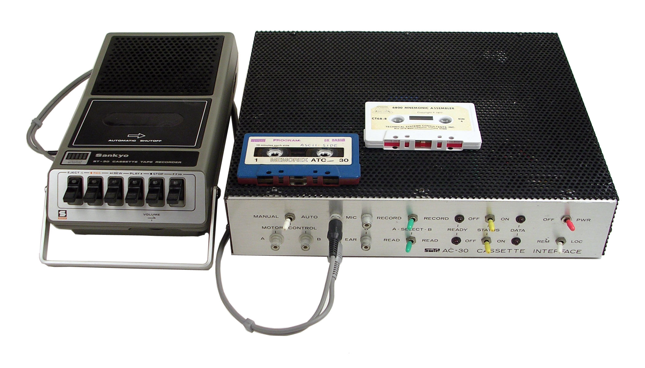
A reproduction SWTPC AC-30 Cassette Interface
I have a couple of Motorola MC6800, MC6802, and MC6809 machines from the 1970's. And I wanted to setup a typical cassette player/recorder setup to save and load code written on these machines.
Note: 2026/10/11 - I hate the way Claude built the human readable schematics. A lot of net lists instead of a nice arrow to the net list. Anyway, so after a bit of double checking I've ordered 5 SMT boards and we'll now see the quality of the designs.
2026/10/11 - The schematics are now drawn with real wires, block by block, instead of a label on every pin. Readable PDFs and PNG images of every sheet and functional block are in kicad-smt/schematic/ (SMT) and kicad/schematic/ (through-hole), for example the SMT modulator:
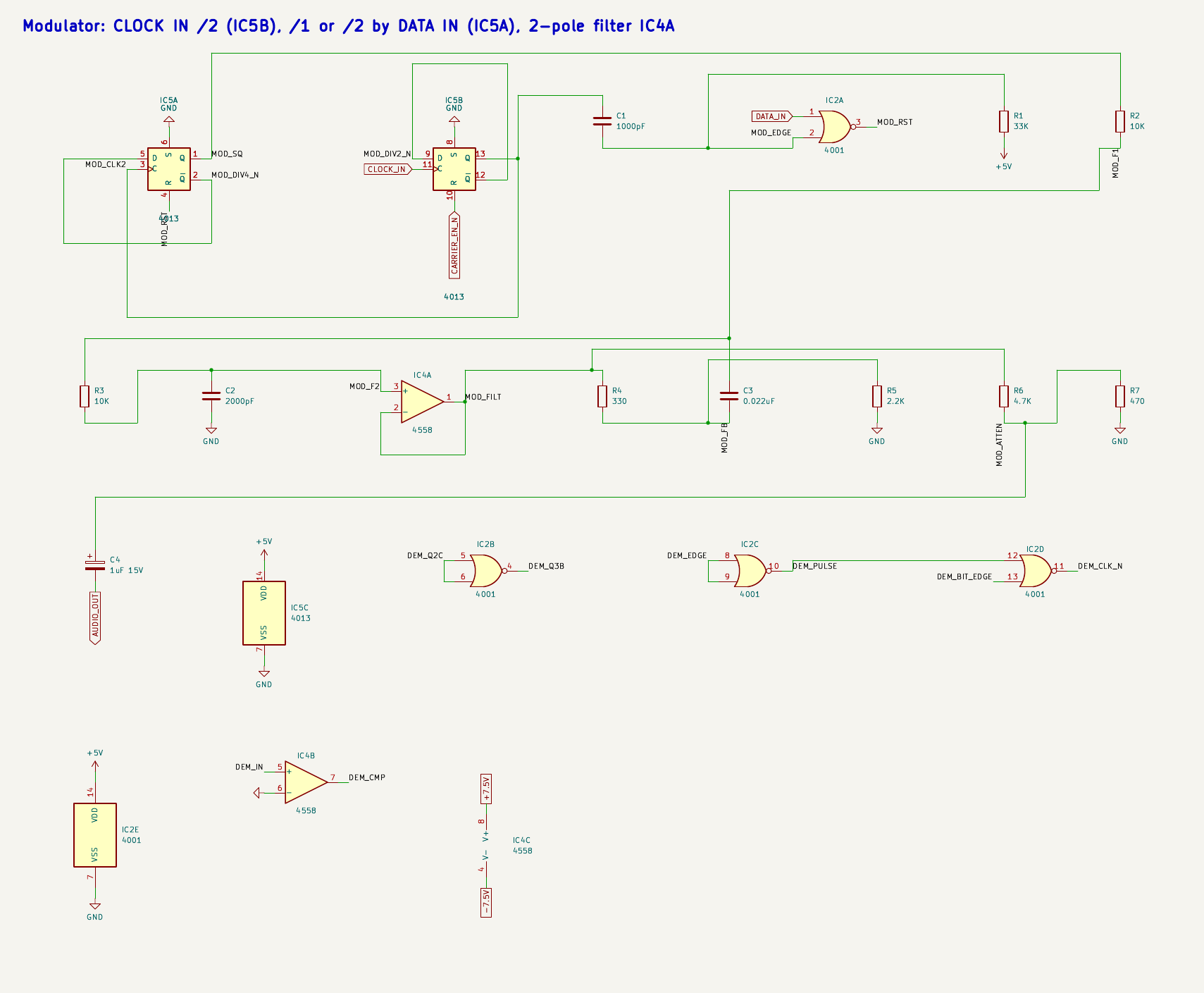
2026/10/10 - Both boards (through-hole kicad/AC30 and SMT kicad-smt/AC30_SMT) now wire the front panel (switches, LEDs, motor jacks, MIC A/B and EAR A/B jacks) to labeled through-hole wire pads instead of the J1/J2 Molex connectors. Board details are in AC30-settings.md and AC30-SMT-settings.md; the parts list is docs/AC30-BOM.md, with Kicad BOMs in kicad/AC30-BOM.csv and kicad-smt/AC30_SMT-BOM.csv.
Board sizes are now 173.0 x 126.5 mm (6.8" x 5.0") through-hole and 173.0 x 88.5 mm (6.8" x 3.5") SMT. Gerbers and drill files for both boards are ready for the board house: kicad/AC30-gerbers.zip (through-hole) and kicad-smt/AC30_SMT-gerbers.zip (SMT, including the top paste layer for a stencil). kicad/tools/build.sh regenerates them on every build, or run kicad/tools/gerbers.sh (add smt for the SMT board).
The SMT board also has a pick-and-place position file, kicad-smt/AC30_SMT-top-pos.csv (SMD parts only, mm, origin at the board's bottom-left corner), to go with the BOM for an assembly house. The through-hole board's layout was re-placed so a fresh build routes completely again; the build now tries other placements automatically if routing ever comes up short. Both boards now have a GND copper fill on both layers (thermal reliefs on the GND pads, so they're still easy to hand-solder; details in the settings files above), added automatically by the build after routing. The motor and relay lines (MOTOR_1A/1B/2A/2B, RELAY_1/2) now use the same 0.6 mm tracks as the power rails, good for roughly 1.5 A. Known issues, including what to check before ordering boards, are listed in KNOWN-ISSUES.md.
2026/10/09 - I've update the PCB to add the mod/demod circuits and a Molex for the power. Additionally I had a new SMT version created.
2026/10/08 - This is my first go around with Claude, Kicad and FreeCAD and creating a PCB to be sent off as Gerbers. I have a lot of inspecting to do. But for a 1st go this is scary impressive.
I gave Claude the following prompts:
Create a kicad schematic for docs/AC30-BOM.md docs/ac30_schematica.jpgand
Save what you have but provide solder pads and labels for the missing power and mod/demodand
Now create the pcb from the schematics. Minimize the board size but leave a safe boarder along the edge.After this I use a few suggested prompts.
Here's what the inside of the Original SWTPC AC30:
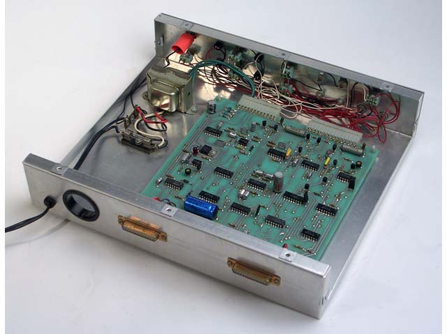
I'd estimate the board to be about 9" x 9" (inches) in size. Here's the schematics I gave Claude:
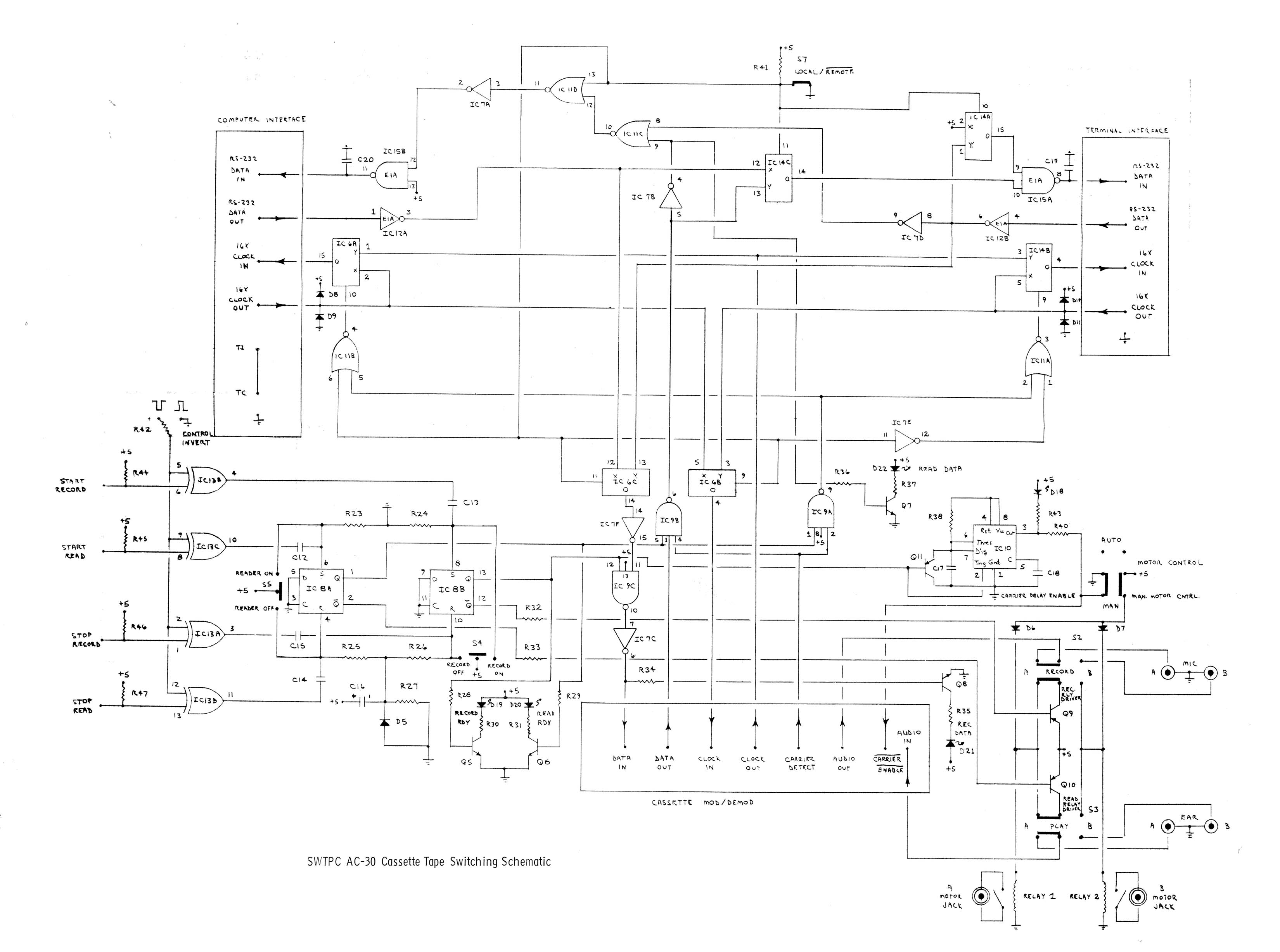
I gave it the AC30/docs/AC30-BOM.md file (simple markdown text file).
Claude started churning and created a 'schematic' (doesn't look like the above, hard to read) and I imported it into the PCB editor. Then didn't make any changes. Instead I let Claude do the rerouting.
I then found out I needed to upgrade Kicad to 10.7 and FreeCAD 26.3 so Claude could create Python 3.11 scripts to build a schematic, the PCB and routing. That was messy as I have Debian Trixie and the latest wants Debian Forky. Anyway, this is the final 1st round attempt. More cleanup to do yet before I ship off the Gerbers.
I'd estimate the size of the new PCB to be about 3.5" x 7" (inches).
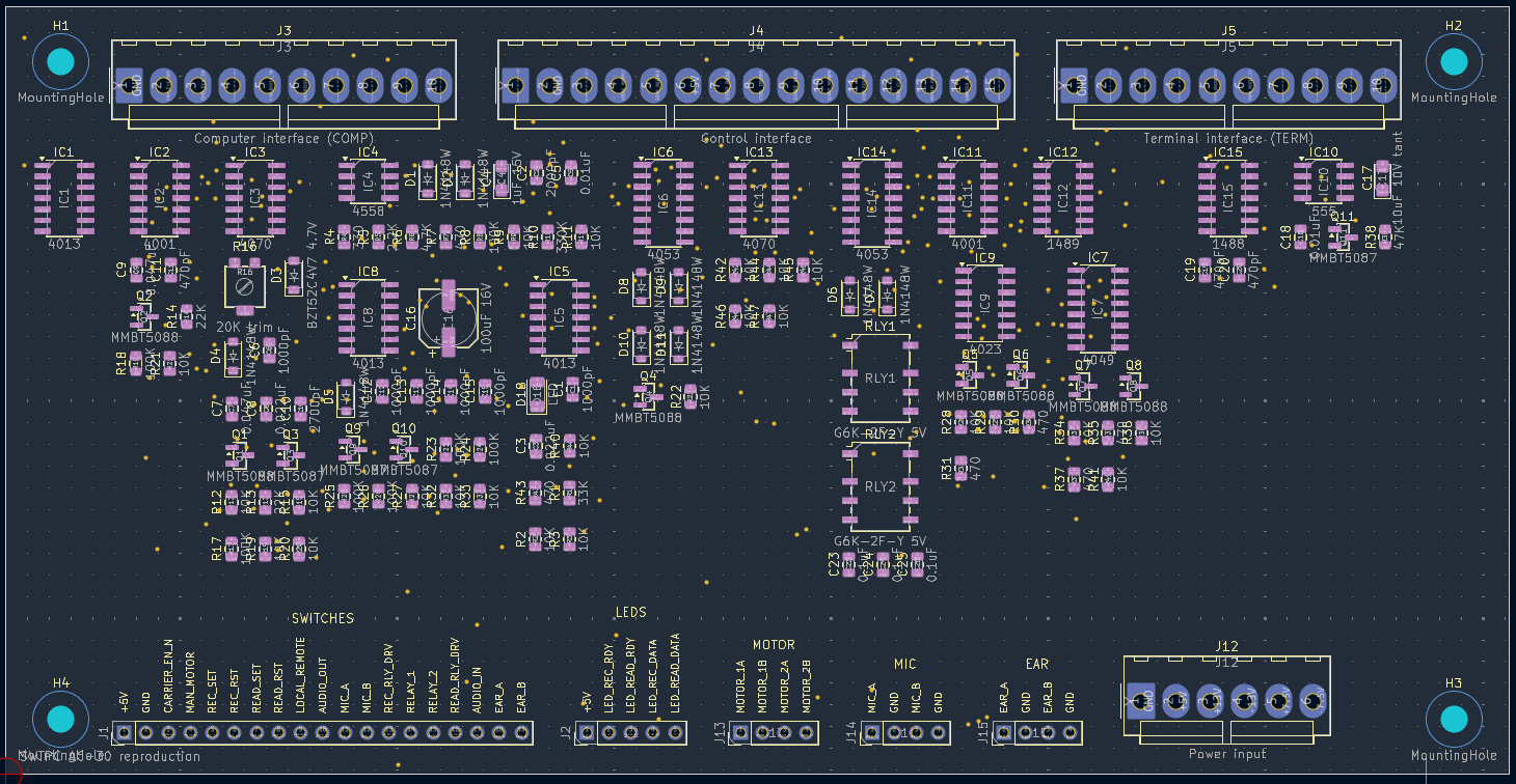
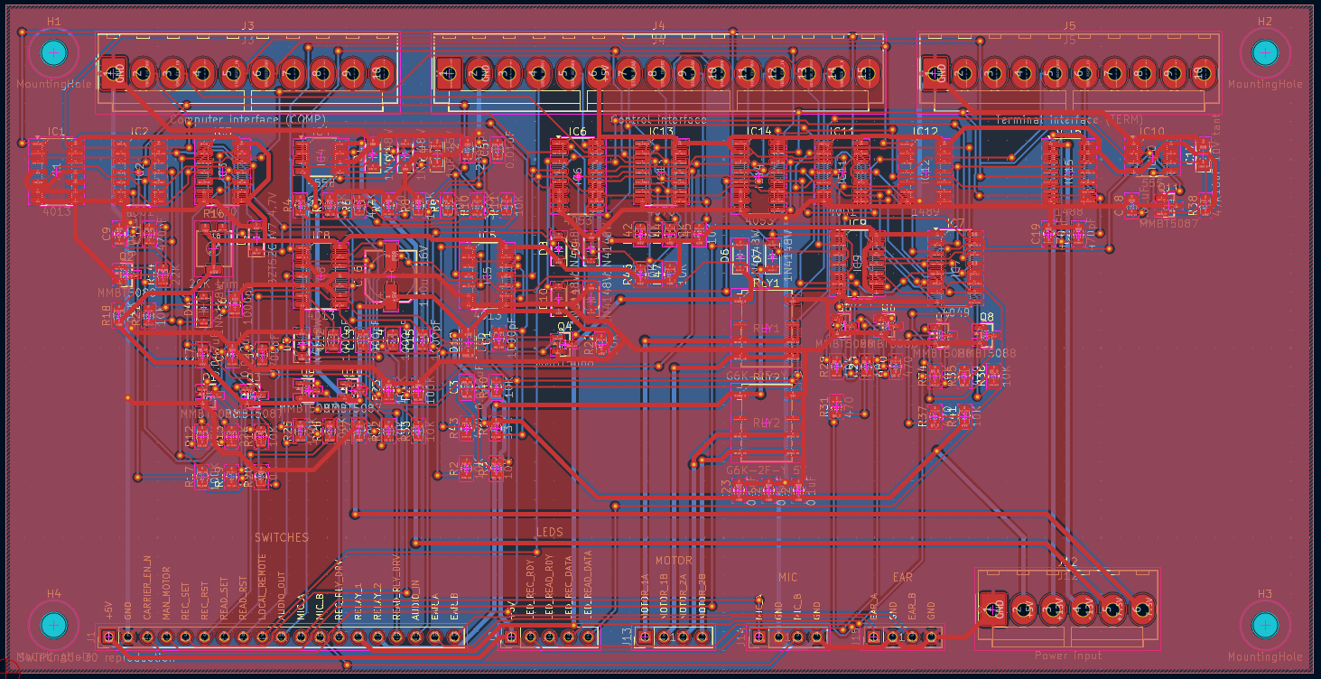
So after several hours, including the Kicad/FreeCAD SNAFU, those are the results. The TPx are where I just dumped a bunch of jumpers I hadn't decided on. I'll fix those later. While it's not done it's a huge jump. It would have taken me about two weeks to get all the parts on the schematic, connections defined and PCB routed.
I stole this from Deramp's AC30 (Mike) site. And he saved it from Mike Holley's original SWTPC site.
| Qty | Value | Footprint | References |
|---|---|---|---|
| 14 | 10K | Resistor_THT:R_Axial_DIN0207_L6.3mm_D2.5mm_P10.16mm_Horizontal | R27, R28, R29, R32, R33, R34, R36, R40, R41, R42, R44, R45, R46, R47 |
| 7 | 1N4148 | Diode_THT:D_DO-35_SOD27_P7.62mm_Horizontal | D5, D6, D7, D8, D9, D10, D11 |
| 5 | 470 | Resistor_THT:R_Axial_DIN0207_L6.3mm_D2.5mm_P10.16mm_Horizontal | R30, R31, R35, R37, R43 |
| 4 | 1000pF | Capacitor_THT:C_Disc_D5.0mm_W2.5mm_P5.00mm | C12, C13, C14, C15 |
| 4 | 100K | Resistor_THT:R_Axial_DIN0207_L6.3mm_D2.5mm_P10.16mm_Horizontal | R23, R24, R25, R26 |
| 4 | 2N5210 | Package_TO_SOT_THT:TO-92_Inline | Q5, Q6, Q7, Q8 |
| 4 | MountingHole | MountingHole:MountingHole_3.2mm_M3 | H1, H2, H3, H4 |
| 3 | 2N5087 | Package_TO_SOT_THT:TO-92_Inline | Q9, Q10, Q11 |
| 2 | 4053 | Package_DIP:DIP-16_W7.62mm | IC6, IC14 |
| 2 | 470pF | Capacitor_THT:C_Disc_D5.0mm_W2.5mm_P5.00mm | C19, C20 |
| 2 | 6V reed relay | Relay_THT:Relay_SPST_StandexMeder_SIL_Form1A | RLY1, RLY2 |
| 1 | +5V (regulated) | Connector_Wire:SolderWire-0.5sqmm_1x01_D0.9mm_OD2.1mm | TP12 |
| 1 | 0.01uF | Capacitor_THT:C_Disc_D5.0mm_W2.5mm_P5.00mm | C18 |
| 1 | 100uF 16V | Capacitor_THT:CP_Radial_D10.0mm_P5.00mm | C16 |
| 1 | 10uF 10V tant | Capacitor_THT:CP_Radial_D6.3mm_P2.50mm | C17 |
| 1 | 1488 | Package_DIP:DIP-14_W7.62mm | IC15 |
| 1 | 1489 | Package_DIP:DIP-14_W7.62mm | IC12 |
| 1 | 16X CLOCK IN (to modulator) | Connector_Wire:SolderWire-0.5sqmm_1x01_D0.9mm_OD2.1mm | TP2 |
| 1 | 16X CLOCK OUT (from demodulator) | Connector_Wire:SolderWire-0.5sqmm_1x01_D0.9mm_OD2.1mm | TP7 |
| 1 | 18 VAC A (from J2 / T1) | Connector_Wire:SolderWire-0.5sqmm_1x01_D0.9mm_OD2.1mm | TP10 |
| 1 | 18 VAC B (from J2 / T1) | Connector_Wire:SolderWire-0.5sqmm_1x01_D0.9mm_OD2.1mm | TP11 |
| 1 | 4001 | Package_DIP:DIP-14_W7.62mm | IC11 |
| 1 | 4013 | Package_DIP:DIP-14_W7.62mm | IC8 |
| 1 | 4023 | Package_DIP:DIP-14_W7.62mm | IC9 |
| 1 | 4049 | Package_DIP:DIP-16_W7.62mm | IC7 |
| 1 | 4070 | Package_DIP:DIP-14_W7.62mm | IC13 |
| 1 | 47K | Resistor_THT:R_Axial_DIN0207_L6.3mm_D2.5mm_P10.16mm_Horizontal | R38 |
| 1 | 555 | Package_DIP:DIP-8_W7.62mm | IC10 |
| 1 | AUDIO IN (to demodulator) | Connector_Wire:SolderWire-0.5sqmm_1x01_D0.9mm_OD2.1mm | TP5 |
| 1 | AUDIO OUT (from modulator) | Connector_Wire:SolderWire-0.5sqmm_1x01_D0.9mm_OD2.1mm | TP4 |
| 1 | CARRIER DETECT (from demodulator) | Connector_Wire:SolderWire-0.5sqmm_1x01_D0.9mm_OD2.1mm | TP8 |
| 1 | Computer interface (COMP) | Connector_Molex:Molex_KK-396_A-41791-0010_1x10_P3.96mm_Vertical | J3 |
| 1 | Control interface | Connector_Molex:Molex_KK-396_A-41791-0015_1x15_P3.96mm_Vertical | J4 |
| 1 | DATA IN (to modulator) | Connector_Wire:SolderWire-0.5sqmm_1x01_D0.9mm_OD2.1mm | TP1 |
| 1 | DATA OUT (from demodulator) | Connector_Wire:SolderWire-0.5sqmm_1x01_D0.9mm_OD2.1mm | TP6 |
| 1 | Front panel harness 1 | Connector_Molex:Molex_KK-396_A-41791-0015_1x15_P3.96mm_Vertical | J1 |
| 1 | Front panel harness 2 | Connector_Molex:Molex_KK-396_A-41791-0012_1x12_P3.96mm_Vertical | J2 |
| 1 | GND (mod/demod) | Connector_Wire:SolderWire-0.5sqmm_1x01_D0.9mm_OD2.1mm | TP9 |
| 1 | GND (power) | Connector_Wire:SolderWire-0.5sqmm_1x01_D0.9mm_OD2.1mm | TP13 |
| 1 | LED | LED_THT:LED_D5.0mm | D18 |
| 1 | RS-232 V+ (IC15 pin 14) | Connector_Wire:SolderWire-0.5sqmm_1x01_D0.9mm_OD2.1mm | TP14 |
| 1 | RS-232 V- (IC15 pin 1) | Connector_Wire:SolderWire-0.5sqmm_1x01_D0.9mm_OD2.1mm | TP15 |
| 1 | Terminal interface (TERM) | Connector_Molex:Molex_KK-396_A-41791-0010_1x10_P3.96mm_Vertical | J5 |
| 1 | ~{CARRIER ENABLE} (to modulator) | Connector_Wire:SolderWire-0.5sqmm_1x01_D0.9mm_OD2.1mm | TP3 |
It measures 173 × 97.5 mm and has 2 copper layers, 1.6 mm thick.
84 parts. The full list of its parts is on this page, with links to each part's symbol and footprint where PCBKit's library has them.
From the linuxha/AC30 repository on GitHub, at the commit this page was made from: the board is AC30-Kicad/AC30.kicad_pcb and its schematic AC30-Kicad/AC30.kicad_sch. PCBKit opens the board in the browser, with nothing to install.
Its repository states no licence, so its author keeps all rights: ask linuxha before reusing the design.


pcbreflux/espressif
all espressif stuff will committed here

CRImier/MyKiCad
My KiCad boards. Can't be bothered uploading individually anymore, so here you go.


Rack-Robotics/Powercore-V1.0-Hardware
CAD & Electronics for Powercore V1

esp-cpp/esp-box-emu
Star Wars: Dark Forces, Doom, NES, Gameboy/Color, Sega Master System / GameGear, Sega Genesis / MegaDrive, and MSX I/II Emulators running on ESP BOX and ESP BOX-3 with a custom gamepad


Redherring32/OpenTendo-TopLoader
An Open Source HardWare (OSHW) recreation of the 1993 toploading NES motherboard (Also known as NES-101)