2 layers119.1 × 80.4 mm
CandleLightfd S01 3x3
linux-automation/candleLightFD
USB CAN-FD interface based on the STM32G0 that works well with gs_usb on Linux
375 parts62

 linux-automation/candleLightFD62
USB CAN-FD interface based on the STM32G0 that works well with gs_usb on Linux
CandleLightfd S01 is an open-source printed circuit board by linux-automation, from the linux-automation/candleLightFD repository on GitHub. It is a 2-layer board of 37.7 × 20 mm with 45 parts on 62 nets, routed with 343 tracks and 32 vias.
It is built around the STM32G0B1CBT6, TJA1051T/3 and KPT-1608SGC, with the KPT-1608EC among its other parts. Its parts include 11 capacitors, 8 resistors, 4 ICs, 4 crystals and 3 diodes. It belongs with the STM32 boards of this library.


candleLight FD is a modern, CAN-FD capable version of the candleLight based on a STM32G0B1 microcontroller.
Out of the box it comes with a single CAN channel placed. But footprints for a second CAN channel are available.
The candleLight FD is - like the candleLight - licensed under the CERN OHL v1.2 open hardware license.
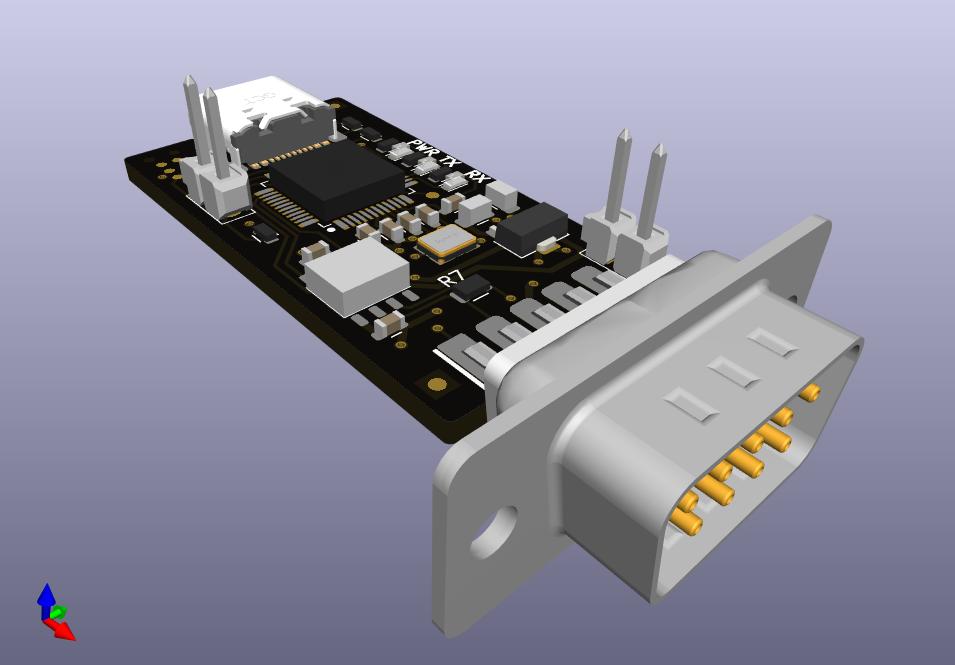
The candleLight FD is available from Linux Automation as a SMD-assembled and functionally tested kit.
The candleLight FD uses a USB-C (USB 2 only) connector to connect to your PC.
CAN is provided on the industry standard D-SUB9 pinout:
Manufacturing Data | Schematic | Interactive BOM
(This is the current release.)
Release Notes:
The firmware is based on the candleLight_fw.
Select the board config BOARD_candleLightFD when building the firmware.
NOTE: We are currently upstreaming our changes to the candleLight_fw repository. While doing so you can find our sources here.
Everyday programming can be done via USB.
Simply invoke dfu-util while the device is running.
More information on flashing can be found in the
firmware repository.
In case the device is bricked: Short the two pins labeled BOOT while powering on the device. The CPU will start in serial download mode.
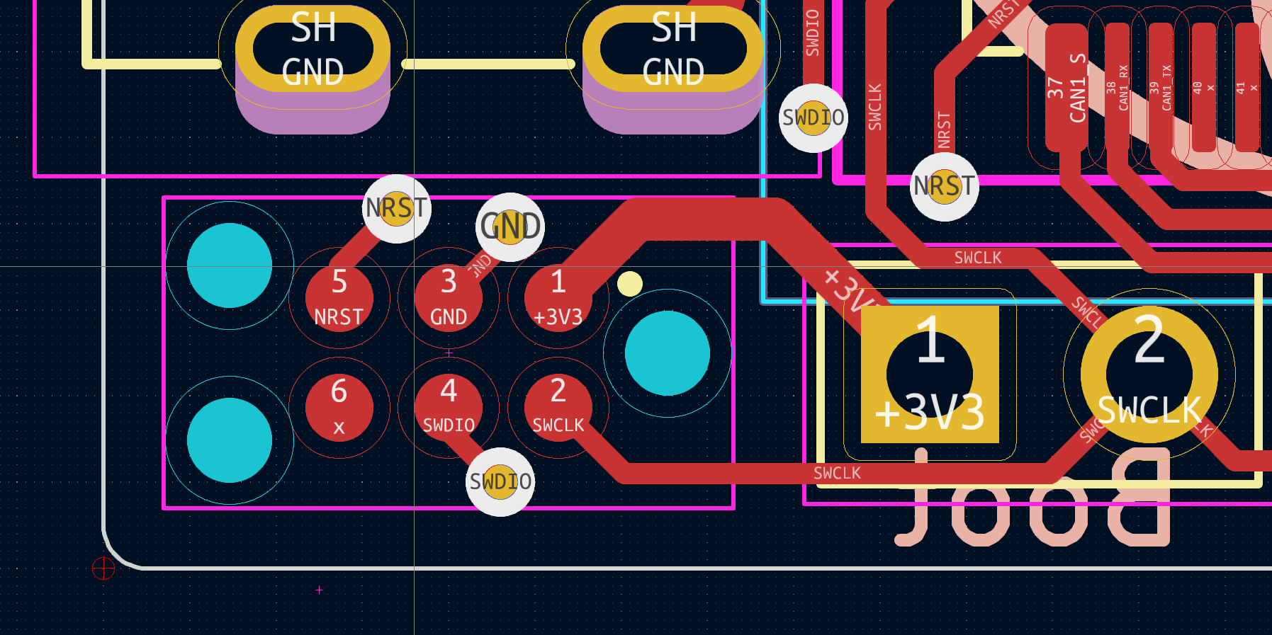
For debugging a single wire interface is exposed on X3. It can be connected using a Tag Connect TC2030-IDC-NL adapter. The pinout is derived from the CandleLight.
The pinout is:
* Pin 1: 3V3
* Pin 2: SWCLK
* Pin 3: GND
* Pin 4: SWDIO
* Pin 5: NRST
* Pin 6: (not connected)
This picture shows X3 on the device. X3 is the connector in the lower left corner - below the USB-C connector.
| Qty | Value | Footprint | References |
|---|---|---|---|
| 4 | 100n_0603_X7R_10%_50V_-40C..125C_Chip-Capacitor | Capacitors_SMD:C_0603 | C8, C9, C10, C11 |
| 4 | Tab | kikit:Tab | T101, T102, T103, T104 |
| 3 | 100n | Capacitors_SMD:C_0603 | C3, C4, C5 |
| 3 | 1k_0603_100mW_1%_E24_Chip-Resistor | Resistors_SMD:R_0603 | R3, R4, R5 |
| 3 | TP2.0mm | Connector_generic:TP2.0mm | TP1, TP2, TP3 |
| 2 | 10u_0805_X7R_10%_10V_-40C..125C_Chip-Capacitor | Capacitors_SMD:C_0805 | C6, C7 |
| 2 | 120R_0805_125mW_1%_E24_Chip-Resistor | Resistors_SMD:R_0805 | R7, R8 |
| 2 | 5k1_0603_100mW_1%_E24_Chip-Resistor | Resistors_SMD:R_0603 | R1, R2 |
| 2 | 6p2_0603_C0G_5%_50V_-40C..125C_Chip-Capacitor | Capacitors_SMD:C_0603 | C1, C2 |
| 2 | CONN_01X02 | Connector_generic:Header_1x2_Pitch2.54mm | P1, P2 |
| 2 | KPT-1608SGC | LEDs_Kingbright:LED_Kingbright_0603 | D1, D2 |
| 2 | Passermarke_1mm_1.8mmx1.8mm | mechanical:Passermarke_1mm_1.8mmx1.8mm | NB3, NB4 |
| 2 | TJA1051T3 | tssop:SOIC-8_3.90mmx4.90mm_Pitch1.27mm | U3, U4 |
| 2 | TP1.0mm | Connector_generic:TP1.0mm | TP4, TP5 |
| 1 | 10k_0603_100mW_1%_E24_Chip-Resistor | Resistors_SMD:R_0603 | R6 |
| 1 | 629722000214_pasteInHole | Socket_GCT:USB4105_pasteInHole | X1 |
| 1 | 830055299 | crystal:Crystal_4Pin_SMD_3.2mmx2.5mm | Y1 |
| 1 | KPT-1608EC | LEDs_Kingbright:LED_Kingbright_0603 | D3 |
| 1 | LAG_Rocket | mechanical:lag_rocket_14.5mmx15mm | NB1 |
| 1 | LAYERSTACK_TB | mechanical:LAYERSTACK_TB | NB2 |
| 1 | MCP1754ST-3302E/MB | TO_SMD:SOT-89 | U2 |
| 1 | STM32G0B1CBT | QFP:LQFP-48_7mmx7mm_Pitch0.5mm | U1 |
| 1 | TC2030-NL | Connector_Tag-Connect:TC2030-NL | X3 |
| 1 | ~ | d-sub:D-SUB-9_side | X2 |
linux-automation/candleLightFD
USB CAN-FD interface based on the STM32G0 that works well with gs_usb on Linux

fake-name/cfs-reverse-engineering
Reverse engineering the Creality CFS for use as a general AMU/MMU system

bluesatunsw/owr
This repo includes all software necessary to operate the Test Rover Platform that is being designed and developed in the 502 project.

Prajwal-sahyadri-ECE/-Optimized-Powersupply-design-
A highly detailed PCB to maintain an power supply for a defined hardware architecture specifically for ICS system

PranavNedunghat/Jetson-Carrier-PX4-Fusion-
This project contains open hardware design files for a baseboard supporting the NVIDIA Jetson Nano, Xavier NX and TX2 NX SoMs.


dhruxraj/stm32-can-ecu
A compact, "ECU-style" CAN node for learning and prototyping automotive-type embedded software. It has an STM32G4 MCU, a CAN transceiver with protection and switchable termination, a 6-axis IMU, a protected 8-18 V…

PurkkaKoodari/ktane-hw
Fully playable hardware implementation of Keep Talking and Nobody Explodes. Mirror of https://gitlab.com/PurkkaKoodari/ktane-hw

It measures 37.7 × 20 mm and has 2 copper layers, 1.6 mm thick.
45 parts, built around the STM32G0B1CBT6, TJA1051T/3, KPT-1608SGC and KPT-1608EC. The full list of its parts is on this page, with links to each part's symbol and footprint where PCBKit's library has them.
From the linux-automation/candleLightFD repository on GitHub, at the commit this page was made from: the board is candleLightfd-S01.kicad_pcb and its schematic MCU.kicad_sch. PCBKit opens the board in the browser, with nothing to install.
Its repository states no licence, so its author keeps all rights: ask linux-automation before reusing the design.