
4 layers42 × 42 mm
 lightside-instruments/powermod
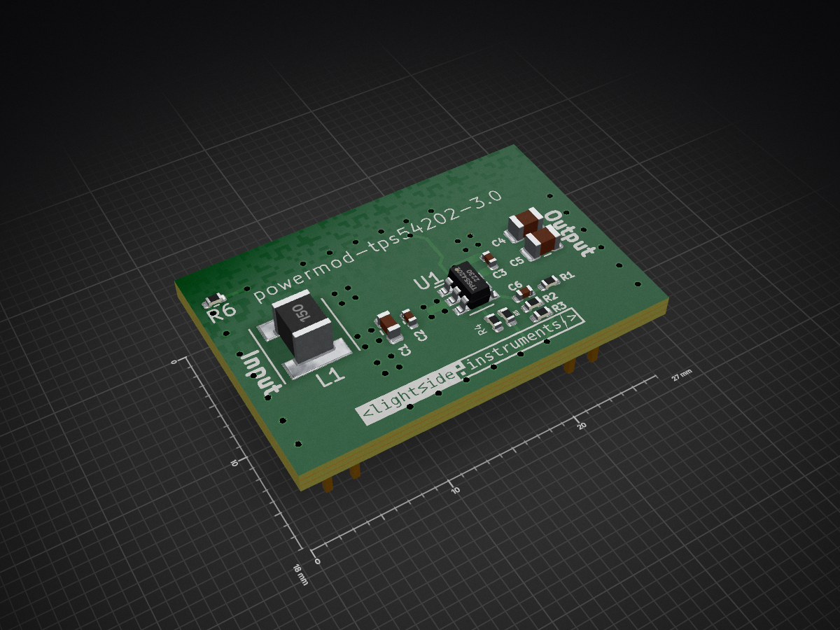
powermod-tps54202 is a simple DC-DC regulator board developed by Lightside Instruments AS.
Powermod is an open-source printed circuit board by lightside-instruments, from the lightside-instruments/powermod repository on GitHub. It is a 4-layer board of 27 × 18 mm with 17 parts on 12 nets, routed with 39 tracks and 48 vias.
It is built around the TPS54202DDC. Its parts include 6 capacitors, 6 resistors, 2 connectors, 1 IC and 1 inductor.
powermod-tps54202 is a simple DC-DC regulator board developed by Lightside Instruments AS.
The project includes schematic and PCB design files for KiCAD.
The project is published by Lightside Instruments AS under TAPR Open Hardware License. Read the LICENSE file for details.
==Calculating the EN pin resistor pair== According to the tps54202h.pdf (SLVSDG7A – APRIL 2016 – REVISED APRIL 2021) there is a formula for calculating the resistor pair to be used for driving the EN pin:
Here is a matlab script for calculating the values:
v_en_rising=1.28 v_en_falling=1.25 rpd=1000000 ih=1/1000000 v_start=3.1 v_stop=v_start-0.48 r4=((v_en_falling/v_en_rising)v_start-3)/ih r5=r4rpd/((v_start/v_en_rising-1)*rpd-r4)
You can also set r4=10000 ohm and find the coresponding r5 e.g. ~7K
| Qty | Value | Footprint | References |
|---|---|---|---|
| 2 | 0.1uF | Capacitor_SMD:C_0402_1005Metric | C2, C3 |
| 2 | 22uF | Capacitor_SMD:C_0805_2012Metric | C4, C5 |
| 2 | Conn_02x07_Odd_Even | Connector_PinHeader_2.00mm:PinHeader_2x07_P2.00mm_Vertical_SMD | J1, J2 |
| 1 | 0 | Resistor_SMD:R_0402_1005Metric | R6 |
| 1 | 100K | Resistor_SMD:R_0402_1005Metric | R2 |
| 1 | 105K | Resistor_SMD:R_0402_1005Metric | R5 |
| 1 | 10uF | Capacitor_SMD:C_0603_1608Metric | C1 |
| 1 | 13.3K | Resistor_SMD:R_0402_1005Metric | R3 |
| 1 | 15uH | Inductor_SMD:L_Taiyo-Yuden_MD-5050 | L1 |
| 1 | 49.9 | Resistor_SMD:R_0402_1005Metric | R1 |
| 1 | 511K | Resistor_SMD:R_0402_1005Metric | R4 |
| 1 | 75 pF | Capacitor_SMD:C_0402_1005Metric | C6 |
| 1 | G*** | spark:lsi-logo-16mm | svg2mod |
| 1 | TPS54202 | Package_TO_SOT_SMD:SOT-23-6 | U1 |
It measures 27 × 18 mm and has 4 copper layers, 1.6 mm thick.
17 parts, built around the TPS54202DDC. The full list of its parts is on this page, with links to each part's symbol and footprint where PCBKit's library has them.
From the lightside-instruments/powermod repository on GitHub, at the commit this page was made from: the board is powermod.kicad_pcb and its schematic powermod.kicad_sch. PCBKit opens the board in the browser, with nothing to install.
Its repository states no licence, so its author keeps all rights: ask lightside-instruments before reusing the design.

jkramarz/TheTick
The Tick is the next evolution in covert access control system implants for simulating adversary-in-the-middle attacks.

JX5S/DP_aux_emulator
Board for modifying traffic on DP-aux. Specifically, board is made for correcting false information provided by the PSVR2 making it not work on PC. Except for DP-aux, it is a passive extension of USB-C.

lhm0/rotating_display_color
56 LED rotating color display with RP2040 and ESP32 microcontrollers


RobustRobby/RPR-TNC
The SGTL5000 sound chip finds its place beneath the Teensy. It is the 20 (21) pin version, as opposed to the 32 pin version used on the audio shield.


cracked-machine/STM32MP1_TestBoard_RevB
RevB breakout board for STM32MP1 (Dual A7 + M4). All pins routed to 0.1" headers.