Skip to the content
2 layers30 × 49.3 mmUSB PD monitor V1, the printed circuit board in 3D

USB PD monitor V1

lhm0/pd_logger82

This repository contains two DIY gadgets to monitor and log USB-C Power Delivery (PD). Both devices are designed to be easy to build, hackable, and useful for makers who want to explore USB-C PD.

Size
30 × 49.3 mm
Copper layers
2
Thickness
1.6 mm
Parts
34
Nets
70
Pads
160
Tracks, vias
404, 151
Pours
1
Routed
Yes
KiCad
KiCad 9.0 (file 20241229)
Created
30 Aug 2025
Updated
9 Feb 2026

Overview

USB PD monitor V1 is an open-source printed circuit board by lhm0, from the lhm0/pd_logger repository on GitHub. It is a 2-layer board of 30 × 49.3 mm with 34 parts on 70 nets, routed with 404 tracks and 151 vias.

It is built around the STM32F103C8T6, AP63203WU and B5819W. Its parts include 14 capacitors, 7 ICs, 5 resistors, 3 diodes and 3 connectors. It belongs with the power boards and the STM32 boards of this library.

Main components

3

README

readme.md

USB-C Power Delivery Measurement Tools

This repository contains two DIY gadgets to monitor and log USB-C Power Delivery (PD).
Both devices are designed to be easy to build, hackable, and useful for makers who want to explore USB-C PD.

Update 01.01.2026: MQTT implemented

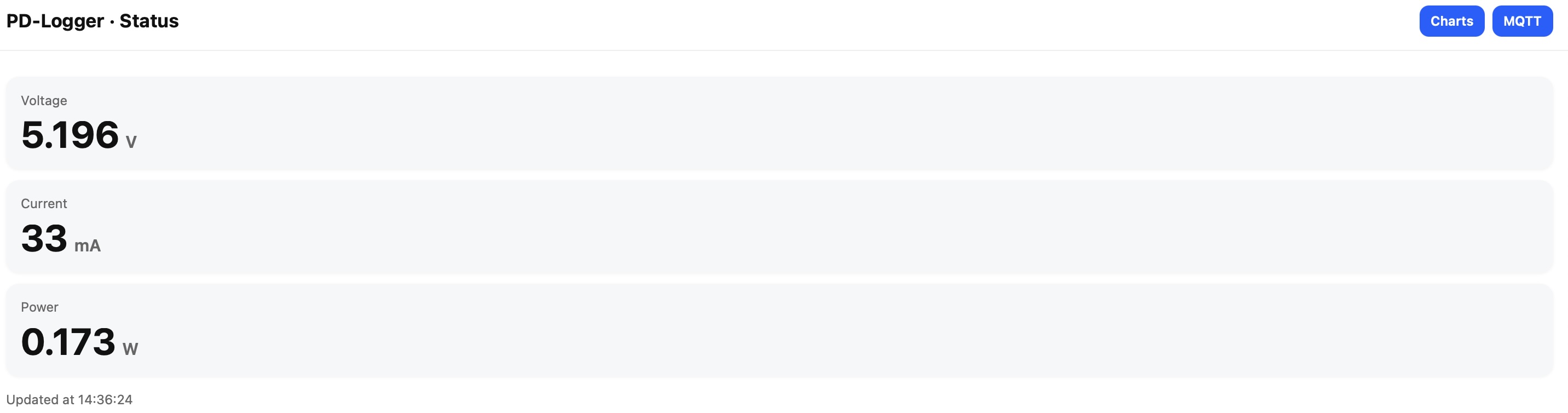
I was asked by @simonsayshomeassistant whether PD Logger could be connected using MQTT. The answer was "no", but I really liked the idea and therefore implemented the MQTT feature today.

I have added a MQTT button to the web interface:
DIY Power Meter

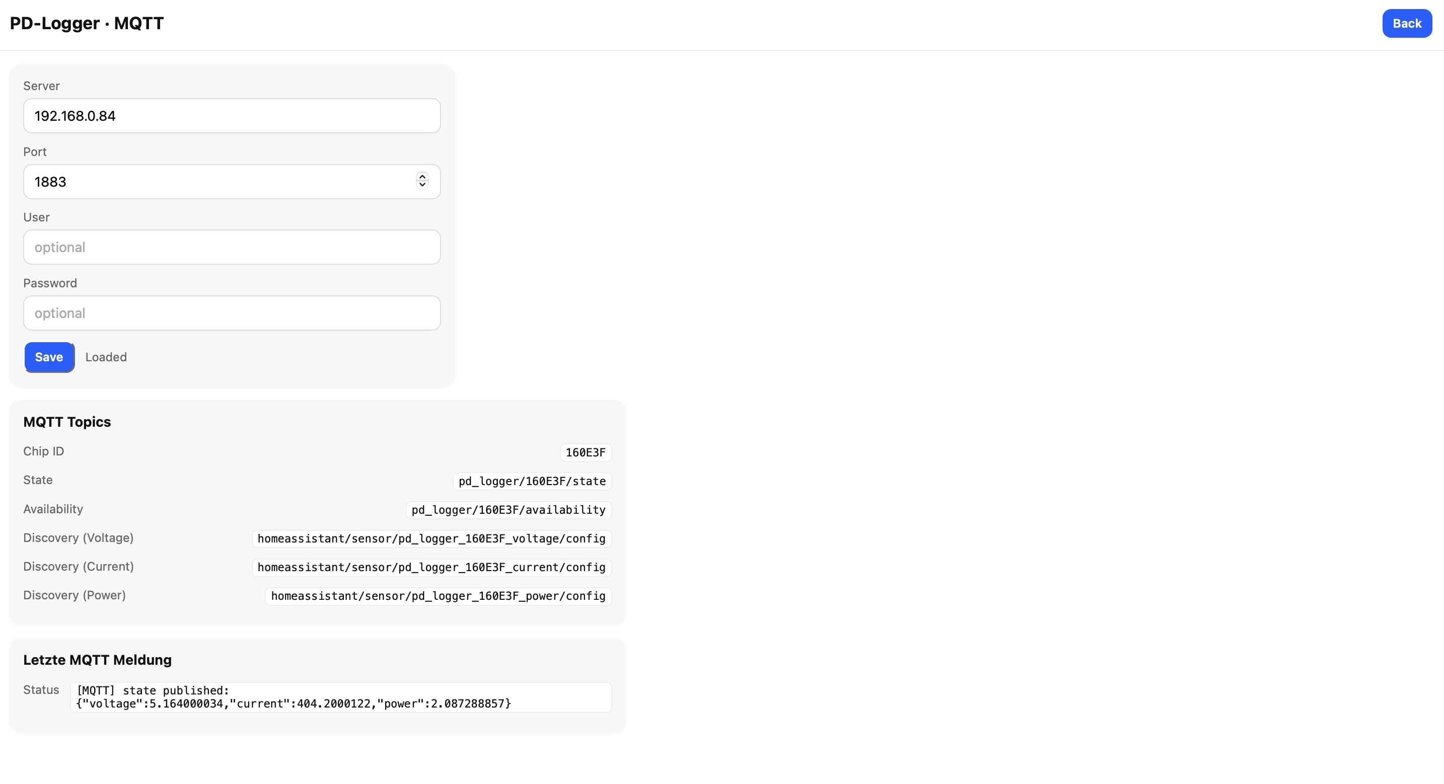
It starts the MQTT configuration page, which looks like this:
DIY Power Meter

Please note: I have tested MQTT with test.mosquitto.org and with a local mosquitto server. From what I see, it all works fine. However, I have not tested with home assistant, simply because I do not have home assistant and know just little about it. Please provide feedback!

Best regards, Ludwin


✨ Features

  • DIY Power Meter
    Small device with an OLED display showing voltage, current, and power in real time.
    Powered by an STM32 microcontroller.

  • PD Logger
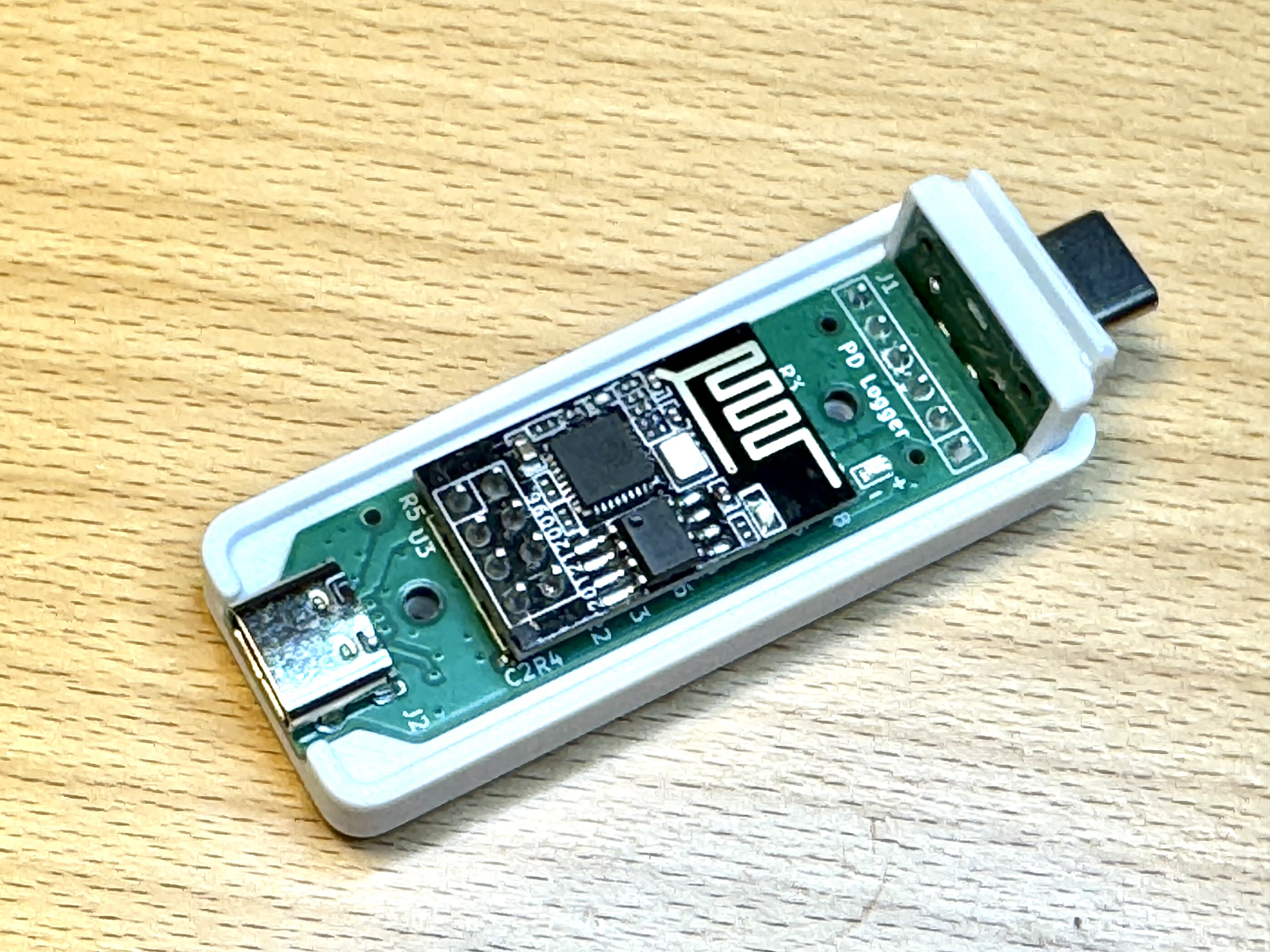
    Wi-Fi enabled device based on ESP-01s.
    Logs voltage, current, and power for several hours and serves interactive plots in any web browser.


📷 Devices

Power Meter
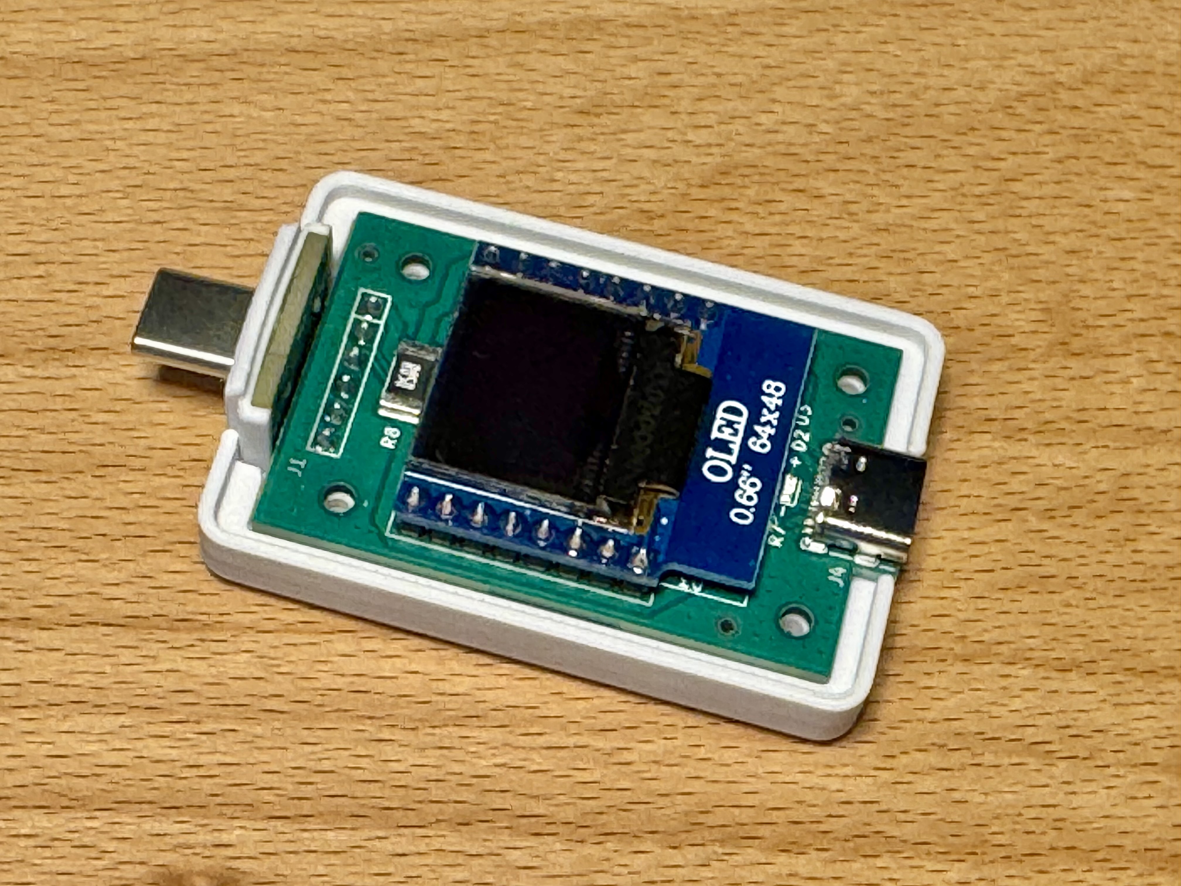
DIY Power Meter

PD Logger

PD Logger

🛠️ How it works

  • USB-C connectors: male on the input side, female on the output side.
  • CC & VCONN lines are passed through to handle PD voltage negotiation.
  • Shunt resistor (50 mΩ) allows precise current measurement.
  • INA219 sensor measures voltage and current via I²C.
  • Step-down converter generates 3.3 V from 5–20 V input.
  • MCUs: STM32 with OLED display (Power Meter), ESP-01s with Wi-Fi (PD Logger).

📦 Hardware

  • Schematics & PCB files → in this repo (/electronics)
  • PCBs manufactured by JLCPCB
  • 3D printable cases → in /mechanics
  • Firmware → in /software

All production data is included in /electronics so you can order, print, and build your own devices.


🌐 Usage

  • Power Meter: plug between charger and device → read values on the display.
  • PD Logger: connect to your local Wi-Fi, then open http://pd-logger.local → see live values.
    • Update interval: 5 seconds
    • Logging capacity: several hours
    • Data download as CSV file
    • Interactive plots for Voltage / Current / Power over time

📄 License

This project is licensed under the
Creative Commons Attribution-NonCommercial-ShareAlike 4.0 International (CC BY-NC-SA 4.0) license.

You are free to share and adapt the material, for non-commercial purposes only,
as long as you provide proper attribution and distribute your contributions under the same license.

For details, see the LICENSE file.


🙌 Acknowledgments

Parts

34
QtyValueFootprintReferences
5100nCapacitor_SMD:C_0402_1005MetricC1, C2, C3, C4, C8
3~my_footprints:JLC_tooling_holeU5, U6, U7
210pCapacitor_SMD:C_0402_1005MetricC9, C10
222µCapacitor_SMD:C_0805_2012MetricC13, C14
22k2Resistor_SMD:R_0402_1005MetricR5, R6
2B5819WDiode_SMD:D_SOD-123D1, D3
10.66inch OLED displaymy_footprints:OLED_display_0_66U3
1100nCapacitor_SMD:C_0603_1608MetricC12
110kResistor_SMD:R_0603_1608MetricR1
110nCapacitor_SMD:C_0402_1005MetricC6
110µCapacitor_SMD:C_0603_1608MetricC5
110µCapacitor_SMD:C_0805_2012MetricC11
116MHzCrystal:Crystal_SMD_3225-4Pin_3.2x2.5mmY1
11kResistor_SMD:R_0402_1005MetricR7
11µCapacitor_SMD:C_0603_1608MetricC7
14µ7Inductor_SMD:L_APV_APH0420L1
150 mOhmResistor_SMD:R_2512_6332MetricR8
1AP63203WUPackage_TO_SOT_SMD:TSOT-23-6U2
1Conn_01x06_Pinmy_footprints:header_90degree_01x06_backJ1
1Debugmy_footprints:4pinJ2
1INA219AxDCNPackage_TO_SOT_SMD:SOT-23-8U4
1STM32F103C8T6Package_QFP:LQFP-48_7x7mm_P0.5mmU1
1USB_C_Receptacle_USB2.0_16Pmy_footprints:USB_C_ReceptacleJ4
1redLED_SMD:LED_0603_1608MetricD2

More from lhm0/pd_logger

2
  • 2 layers16 × 52 mmUSB PD monitor ESP01s, the printed circuit board in 3D

    USB PD monitor ESP01s

    lhm0/pd_logger

    This repository contains two DIY gadgets to monitor and log USB-C Power Delivery (PD). Both devices are designed to be easy to build, hackable, and useful for makers who want to explore USB-C PD.

    25 parts82
  • 2 layers11.5 × 16 mmUSB plug, the printed circuit board in 3D

    USB plug

    lhm0/pd_logger

    This repository contains two DIY gadgets to monitor and log USB-C Power Delivery (PD). Both devices are designed to be easy to build, hackable, and useful for makers who want to explore USB-C PD.

    4 parts82

Similar boards

  • 2 layers46.9 × 46.6 mmFourth, the printed circuit board in 3D

    Fourth

    Bhakti-A/Maya_V_FlightController

    This is a custom flight controller PCB designed for drones.

    84 parts1
  • 2 layers48.1 × 48 mmFlight controller, the printed circuit board in 3D

    Flight controller

    0xmanidev/hackydrone

    this is a drone project made for outpost event

    68 partsMIT
  • 4 layers84 × 66 mmSpinner, the printed circuit board in 3D

    Spinner

    enkhbold470/spinner

    12-24 V FOC BLDC motor controller: STM32G431, three IR2104 half bridges with 60 V MOSFETs, MT6701 encoder, CAN FD. 4-layer KiCad 10 board.

    87 partsCERN-OHL-S-2.0
  • 4 layers102 × 49 mmCURSO PCB DRONE, the printed circuit board in 3D

    CURSO PCB DRONE

    ArduProject/PCB_DRONE_C8

    En este repositorio encontrareis los archivos de fabricación y las listas de montaje del PCB con STM32F103C8 que hemos visto en el curso.

    153 parts1MIT
  • 4 layers96 × 96 mmSTM32F103C8T6, the printed circuit board in 3D

    STM32F103C8T6

    andreabadan/STM32F103_Telemetry_V01

    115 partsGPL-3.0
  • 2 layers55.5 × 45.5 mmSTM32-DevBoard, the printed circuit board in 3D

    STM32-DevBoard

    maxai472/STM32-DevBoard

    56 parts
  • 4 layers84 × 42 mmMFW007B, the printed circuit board in 3D

    MFW007B

    westrik/MFW007B

    NA-01 Rev B (for JLCPCB assembly)

    96 parts

Questions

How big is the USB PD monitor V1 PCB?

It measures 30 × 49.3 mm and has 2 copper layers, 1.6 mm thick.

What parts does the USB PD monitor V1 use?

34 parts, built around the STM32F103C8T6, AP63203WU and B5819W. The full list of its parts is on this page, with links to each part's symbol and footprint where PCBKit's library has them.

Where can I download the USB PD monitor V1 KiCad files?

From the lhm0/pd_logger repository on GitHub, at the commit this page was made from: the board is electronics/USB_PD_monitor_STM32_V1/USB_PD_monitor_V1.kicad_pcb and its schematic electronics/USB_PD_monitor_ESP01s/MCU.kicad_sch. PCBKit opens the board in the browser, with nothing to install.

Can I use the USB PD monitor V1 design in my own project?

Its repository states no licence, so its author keeps all rights: ask lhm0 before reusing the design.