2 layers54 × 78.8 mm

 lhm0/marvin_robot2
robot model controlled by ESP32
Marvin PS is an open-source printed circuit board by lhm0, from the lhm0/marvin_robot repository on GitHub. It is a 2-layer board of 67 × 45 mm with 20 parts on 42 nets, routed with 358 tracks and 87 vias.
It is built around the TPS63070RNM, 74HC595 and ULN2803A. Its parts include 5 ICs, 3 capacitors, 3 resistors, 3 connectors and 1 diode. It belongs with the robots and motor control boards of this library.


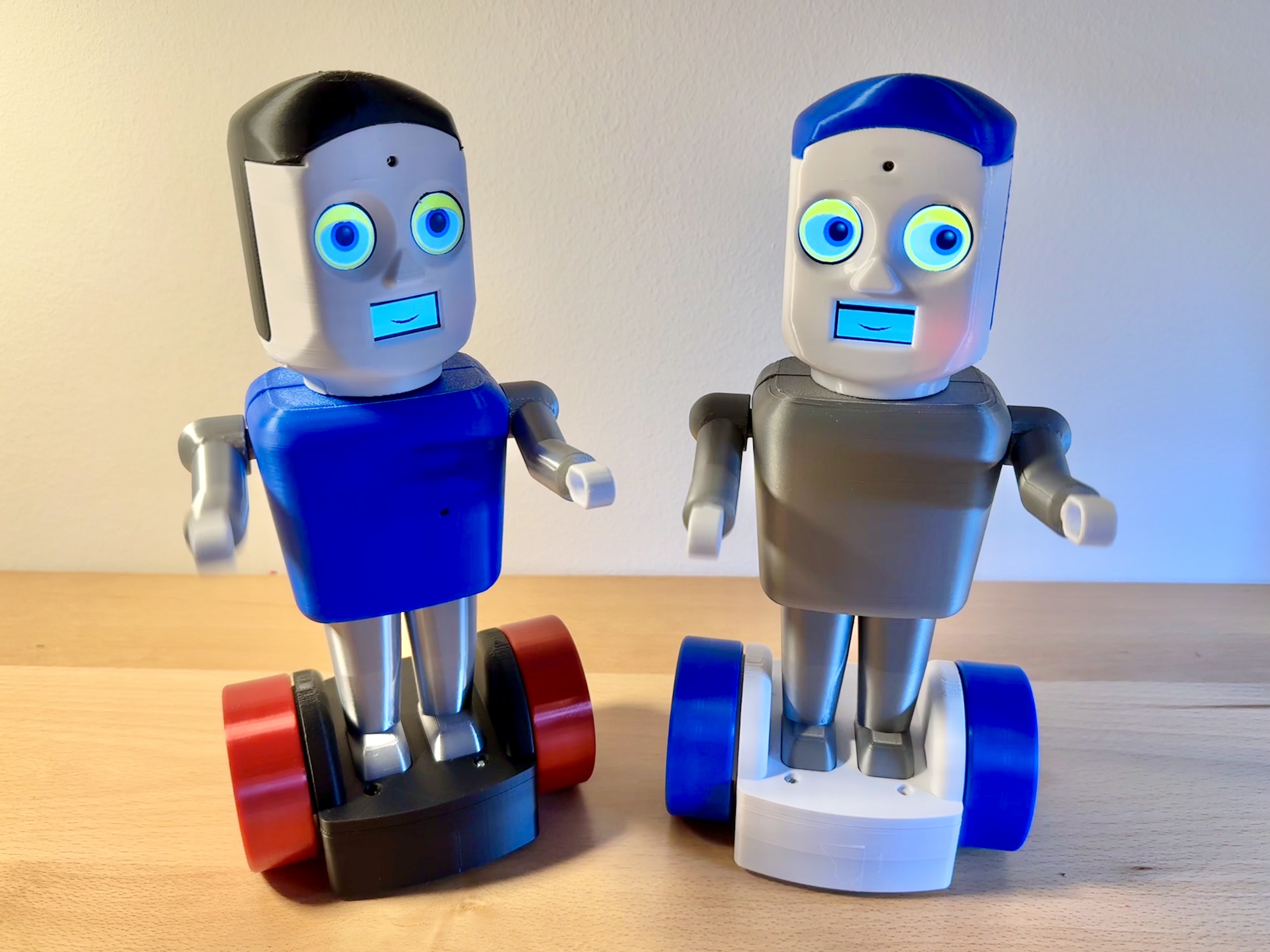
This repository contains all development data for an ESP32-based, fully 3D-printed toy robot featuring an animated face, sound output, and WiFi control.
The project combines mechanical design, electronics, and embedded software in a modular and replication-friendly architecture. It was designed for hobbyists, education, and non-commercial use, with a strong focus on availability of components and ease of assembly.
The robot features:
All mechanical parts are fully 3D-printed and were designed using Autodesk Fusion.
The electronics are organized on two custom two-layer PCBs, avoiding SMD components to simplify manual assembly.
The robot is built around a two-module electronic architecture:
Both modules are connected via a 10-pin ribbon cable.
The firmware is written in C++ and based on FreeRTOS.
It handles:
The software is built using:
See SYSTEM_OVERVIEW.md in the repository for detailed software documentation.
marvin_robot
├─ documentation
│  ├─ datasheets
│  └─ images
│     ├─ electronics
│     ├─ eye_images
│     ├─ mechanics
│     └─ software
├─ electronics
│  ├─ marvin_MCU
│  │  ├─ marvin_MCU-backups
│  │  └─ production
│  │     └─ backups
│  └─ marvin_PS
│     ├─ marvin_PS-backups
│     └─ production
│        └─ backups
├─ mechanics
│  └─ stl_files
│     ├─ base
│     ├─ body
│     ├─ head
│     └─ legs
└─ software⚠️ Li-ion safety:
Handle batteries with care. Avoid short circuits, mechanical damage, and overheating.
This project is open source for:
❌ Commercial use is not permitted.
Happy building! 🤖✨
| Qty | Value | Footprint | References |
|---|---|---|---|
| 2 | 100k | Resistor_THT:R_Axial_DIN0207_L6.3mm_D2.5mm_P10.16mm_Horizontal | R5, R8 |
| 2 | 100nF | Capacitor_THT:C_Rect_L10.0mm_W2.5mm_P7.50mm_MKS4 | C2, C3 |
| 2 | 28BYJ_48 | Connector_JST:JST_XH_B5B-XH-A_1x05_P2.50mm_Vertical | M1, M2 |
| 1 | 10 pin IDC connector | Connector_IDC:IDC-Header_2x05_P2.54mm_Vertical | J3 |
| 1 | 1k | Resistor_THT:R_Axial_DIN0207_L6.3mm_D2.5mm_P10.16mm_Horizontal | R1 |
| 1 | 4017 | Package_DIP:DIP-16_W7.62mm | U7 |
| 1 | 470µF | my_footprints:CP_Radial_D10.0mm_P5.00mm_slim_silkscreen | C1 |
| 1 | 74HC595 | Package_DIP:DIP-16_W7.62mm | U1 |
| 1 | LED | LED_THT:LED_D3.0mm | D1 |
| 1 | SW_MEC_5G | my_footprints:OmronTaster | SW1 |
| 1 | TPS63070 | my_footprints:TPS63070_breakout | U4 |
| 1 | ULN2803A | Package_DIP:DIP-18_W7.62mm | U2 |
| 1 | VBUS input | my_footprints:connector_2pin | J2 |
| 1 | battery | Connector_JST:JST_XH_B2B-XH-A_1x02_P2.50mm_Vertical | J1 |
| 1 | charging control | my_footprints:TP4056_breakout | U3 |
| 1 | servo left | my_footprints:Jumper_3pin | M3 |
| 1 | servo right | my_footprints:Jumper_3pin | M4 |


OverInvented/Flippy
The code needed to build a mechanical 7-segment display that uses electromagnets to display characters


niteshkadyan/Hearty-LED-Necklace-Badge
Kicad project files and Android app for the Hearty LED wearable necklace cum badge

julianschick/flipdot-brose
Microcontroller code (ESP32) and Circuit Design for controlling Brose Flipdot Modules.

LudovicLemarinel/EspHomeAutomation
Home Automation based on ESP8266 and MQTT
It measures 67 × 45 mm and has 2 copper layers, 1.6 mm thick.
20 parts, built around the TPS63070RNM, 74HC595 and ULN2803A. The full list of its parts is on this page, with links to each part's symbol and footprint where PCBKit's library has them.
From the lhm0/marvin_robot repository on GitHub, at the commit this page was made from: the board is electronics/marvin_PS/marvin_PS.kicad_pcb and its schematic electronics/28BYJ_48_test/28BYJ_48_test.kicad_sch. PCBKit opens the board in the browser, with nothing to install.
Its repository states no licence, so its author keeps all rights: ask lhm0 before reusing the design.