4 layers74.9 × 98.3 mm

 LesserChance/ArcadeController2
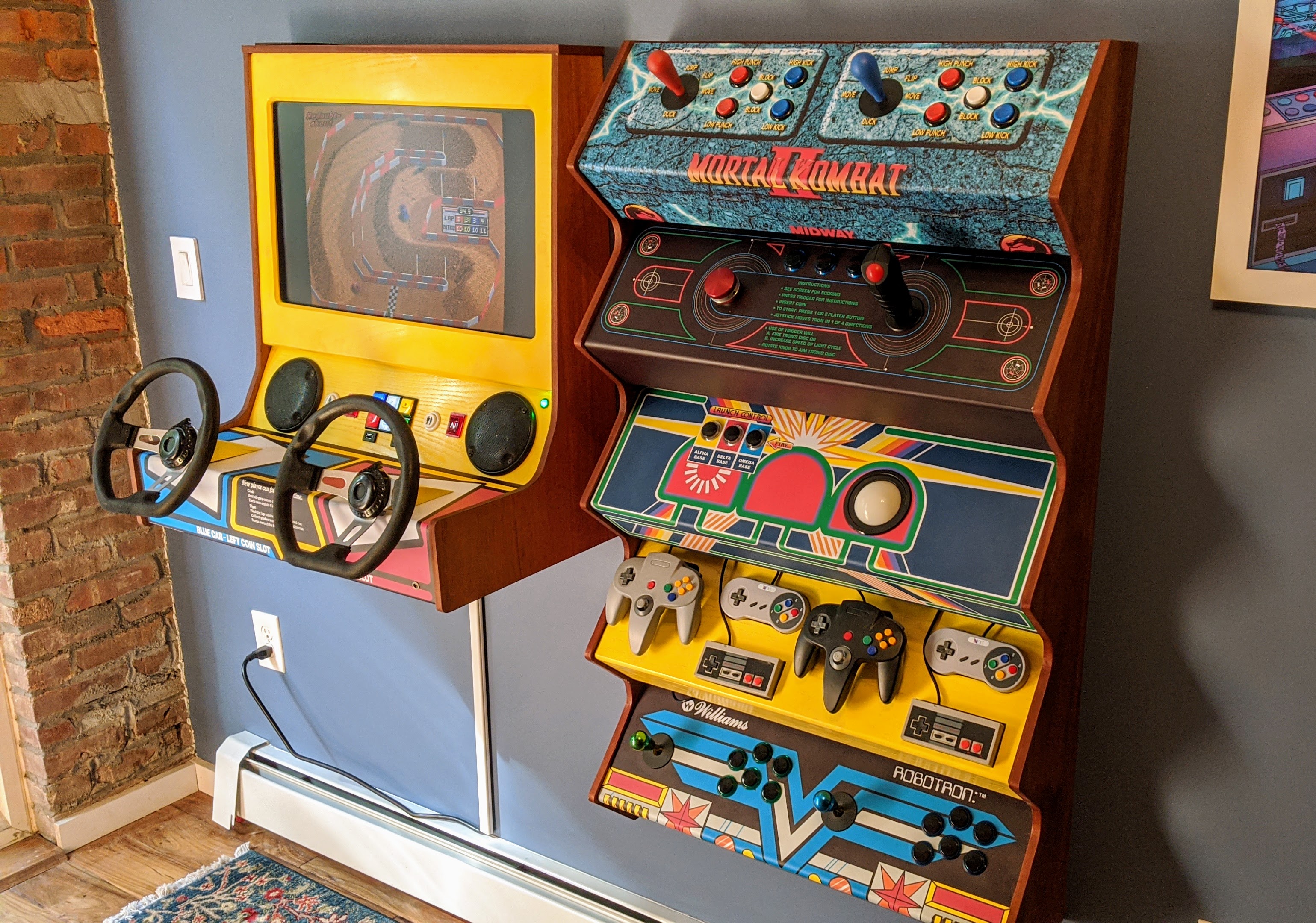
Swappable control panels for a homebuilt arcade
ArcadePanel is an open-source printed circuit board by LesserChance, from the LesserChance/ArcadeController repository on GitHub. It is a 2-layer board of 194.8 × 39.4 mm with 16 parts on 50 nets, routed with 281 tracks and 14 vias.
It is built around the AU-Y1008-2 and SBH11-PBPC-D25-ST-BK. Its parts include 6 connectors, 4 resistors and 1 switch.

The goal of this project is to make an easily-swappable control panel for a homebuilt arcade. There are two PCBs that are designed to mate through a ribbon cable connection. By default, this setup will allow for any control panel to have a maximum of 2 joysticks and 14 buttons (22 total digital inputs), 6 axes (e.g. 6 spinners) and two USB devices. You can easily edit the program on the arduino to assure all of your control panels will work, though, for instance if you need more digital inputs and fewer axes.
As I build out more control panels I'll be adding pictures and diagrams of how everything operates.
One Panel PCB exists for each control panel. The Panel PCB exists as the interface between the controls (joysticks, trackballs, spinners, USB devices) and the Main interface. It is split into various sections. Full wiring diagrams can be found in the docs directory.
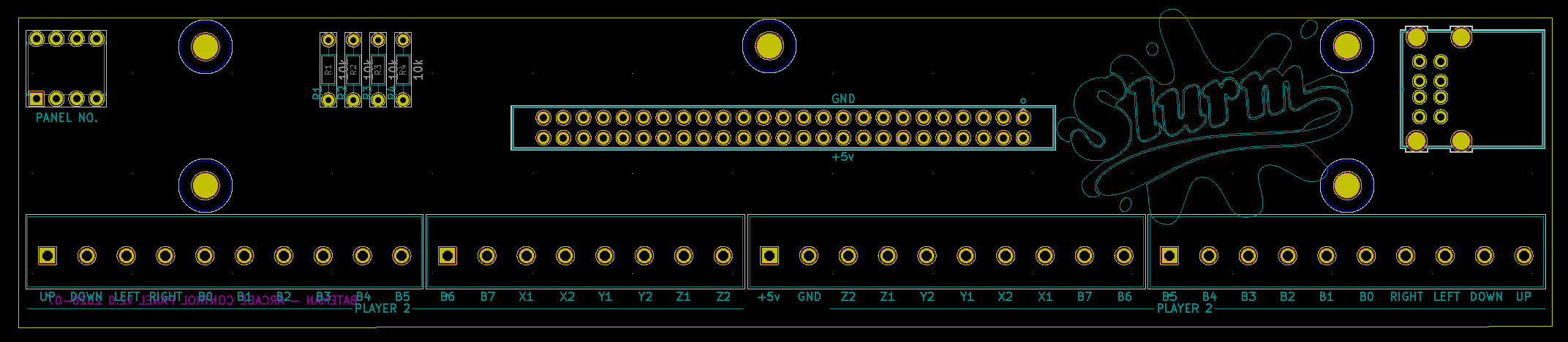
Player One Connected to "Player One" Micro.
Up, Down, Left, Right, B0-5: Four directional wires, 6 button wires. (note that B6, B7 are not wired to anything)
X1, X2, Y1, Y2, Z1, Z2: These utilize interrupt pins on the arduinos, and are used for encoder connections (trackball, spinner)
Player Two Connected to "Player Two" Micro.
Up, Down, Left, Right, B0-5: Four directional wires, 6 button wires. (note that B6, B7 are not wired to anything)
X1, X2, Y1, Y2, Z1, Z2: These utilize interrupt pins on the arduinos, and are used for encoder connections (trackball, spinner)
+5v/Ground Pulls +5v and Ground from "Player One" Micro. Useful for LEDs/etc
USB These directly wire to USB connection on the main control panel. These can be used to directly connect USB devices to your computer. Unfortunately these dont seem to be working just yet!
DIP switch Used to identify which control panel this is. Allows for different programming on the arduinos per control panel.
For detailed wiring information see the pinmap.
The Main PCB is what connects to your computer through USB. In total it requires four open USB ports. Only One Main PCB is necessary. The main panels houses two Arduino Micros.
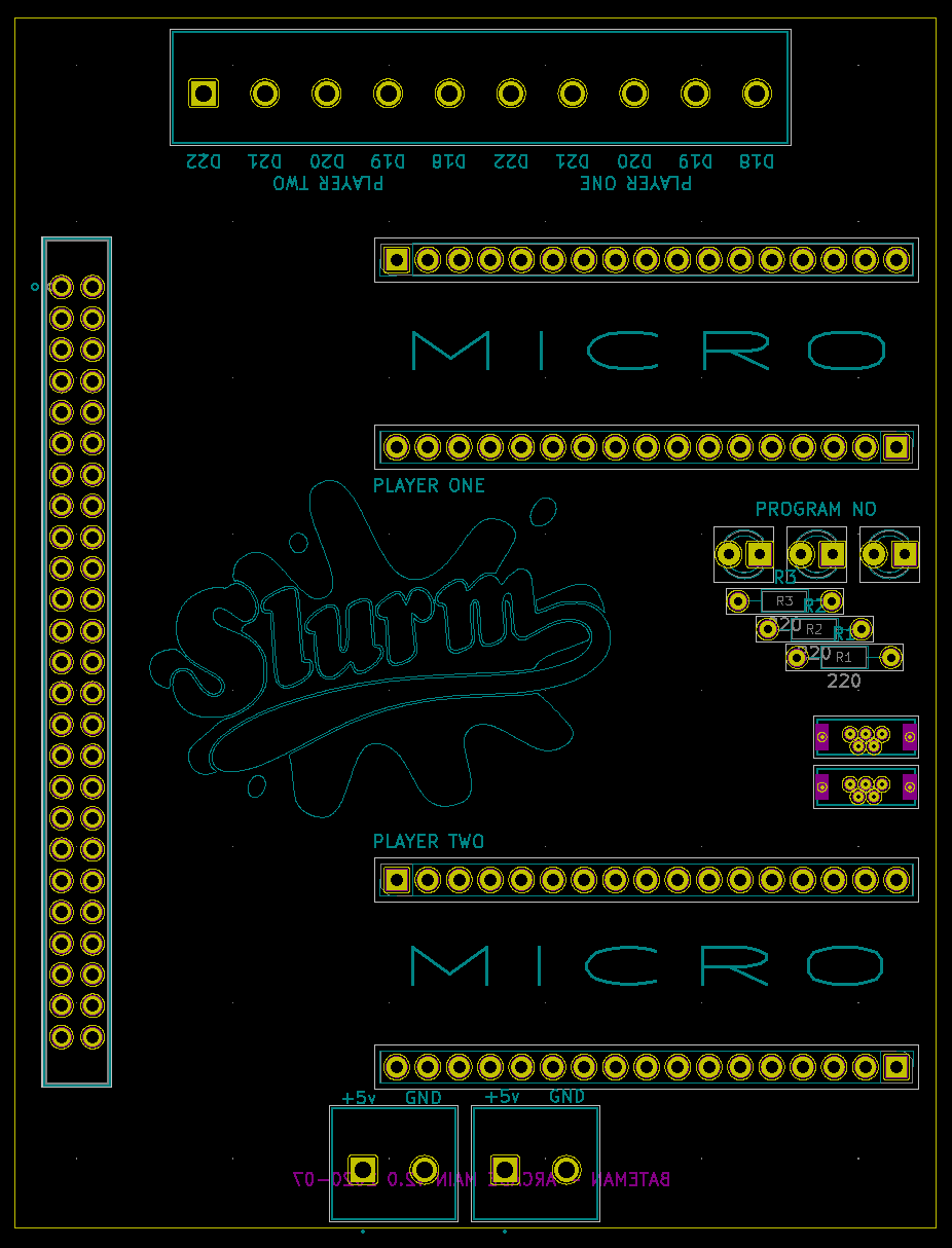
Micro Headers These are the positions where you plug in Arduino Micros.
Screw in Terminals These can be used for shared functions e.g. Player 1/2 Start/Coin as well as menu or function buttons. 6 are connected to "Player One" Micro, and another 6 are connected to "Player Two" Micro.
The program is built to run on an Ardunio Micro. Two Arduino Micros are required for two-player functionality. Player One and the two additional USB devices will work fine with just one, though, if you can get away with a maximum of 17 total digital inputs on any control panel.
When plugged in the Arduinos will be treated as a joystick/mouse/keyboard by the computer based on the code used for the control panel. The joystick, by default is 2 axis (X/Y) and 12 button.
Schematics were designed in Kicad. I print PCBS with JLCPCB.
The pinmap outlines how connections are bridged between the PCBs and how they function by default through USB. Panel->Main->Arduino->Function
The wiring doc outlines standard wiring for trackballs and spinners directly into the Panel PCB.
Prices are USD, do not include shipping, and are as of July 2020.
Buy extra screw-in terminals to make more control panels, and buy the Panel PCBs in bulk. Given the below prices you could create 10 easily-swappable control panels for ~$80, and you may be able to find those screw terminals more cheaply, or decide to bypass those, just solder in your connections and have it all for ~$40. Of course the price of buttons/joysticks/trackballs/steering wheels/etc is additional.
| Component | Part | Supply | Cost | Count |
|---|---|---|---|---|
| Main | Arduino Micro | Ardunio Store | $12.30 | 2 |
| Main | PCB | JLCPCB | $7.00 | 1 (price is per 5 though - minimum order) |
| Main | Micro USB | Digikey | $.87 | 2 |
| Main | Micro Pin Headers | Digikey | $.51 | 2 |
| Main | Micro connection headers | Digikey | $2.95 | 1 (cut each down to 17 pins) |
| Main | LEDs | Im sure you have some laying around | - | 3 |
| Main | Cable Header | Digikey | $4.56 | 1 |
| Panel | PCB | JLCPCB | $12.00 | 1 (price was for 10) |
| Panel | USB Header | Digikey | $1.07 | 1 |
| Panel | Ribbon Cable | Digikey | $3.27 | 1 |
| Panel | Cable Header | Digikey | $1.02 | 1 |
| Panel | DIP Switch | Digikey | $.69 | 1 |
| Main+Panel | Resistors | (3) 10k, 3 (220) | - | 6 |
| Main+Panel | Screw-in Terminal | Digikey | $1.73 | 5 (+4 for each additional panel) |
Why do the PCBs have the Slurm logo on them? I dont know, I just really like Futurama and happened to have this image handy...
| Qty | Value | Footprint | References |
|---|---|---|---|
| 5 | MountingHole_3.2mm_M3 | MountingHole:MountingHole_3.2mm_M3 | 4, 4, 4, 4, 4 |
| 4 | 10k | Resistor_THT:R_Axial_DIN0204_L3.6mm_D1.6mm_P7.62mm_Horizontal | R1, R2, R3, R4 |
| 3 | Screw_Terminal_01x10 | TB001-500-10BE:CUI_TB001-500-10BE | J1, J2, J5 |
| 1 | AU-Y1008-2 | AU-Y1008-2:AU-Y1008-2 | J6 |
| 1 | SBH11-PBPC-D25-ST-BK | ul_SBH11PBPCD25STBK:SBH11-PBPC-D25-ST-BK | J3 |
| 1 | SW_DIP_x04 | digikey-footprints:DIP-8_W7.62mm | SW1 |
| 1 | Screw_Terminal_01x08 | TB001-500-08BE:CUI_TB001-500-08BE | J4 |
It measures 194.8 × 39.4 mm and has 2 copper layers, 1.6 mm thick.
16 parts, built around the AU-Y1008-2 and SBH11-PBPC-D25-ST-BK. The full list of its parts is on this page, with links to each part's symbol and footprint where PCBKit's library has them.
From the LesserChance/ArcadeController repository on GitHub, at the commit this page was made from: the board is PCBs/ArcadePanel/ArcadePanel.kicad_pcb. PCBKit opens the board in the browser, with nothing to install.
Its repository states no licence, so its author keeps all rights: ask LesserChance before reusing the design.

google/mozc-devices
Circuit diagrams and firmware source code for Gboard DIY keyboards

conorpp/u2f-zero
U2F USB token optimized for physical security, affordability, and style

rusefi/rusefi
rusefi - GPL internal combustion engine control unit

VoronDesign/Voron-Hardware
Cool Hardware designed by the Voron Design group

hoglet67/RGBtoHDMI
Bare-metal Raspberry Pi project that provides pixel-perfect sampling of Retro Computer RGB/YUV video and conversion to HDMI

hackclub/OnBoard
💡 Join 1,000 teenagers and make your first PCB with a $100 grant!

