2 layers133 × 123 mm

 leonardoward/gps-development-boards5
Development Board designed with KiCad for the ANTENOVA M20050-1 and the ATGM332D-5N31
Gps testing board is an open-source printed circuit board by leonardoward, from the leonardoward/gps-development-boards repository on GitHub, published under the Apache-2.0 licence. It is a 2-layer board of 107 × 88 mm with 33 parts on 41 nets, routed with 158 tracks and 4 vias.
It is built around the ATGM332D-5N31, M20050-1 and BAT-HLD-001-THM. Its parts include 17 connectors, 4 capacitors, 4 resistors, 2 ICs and 1 diode. It belongs with the radio and wireless and microcontroller boards boards of this library.


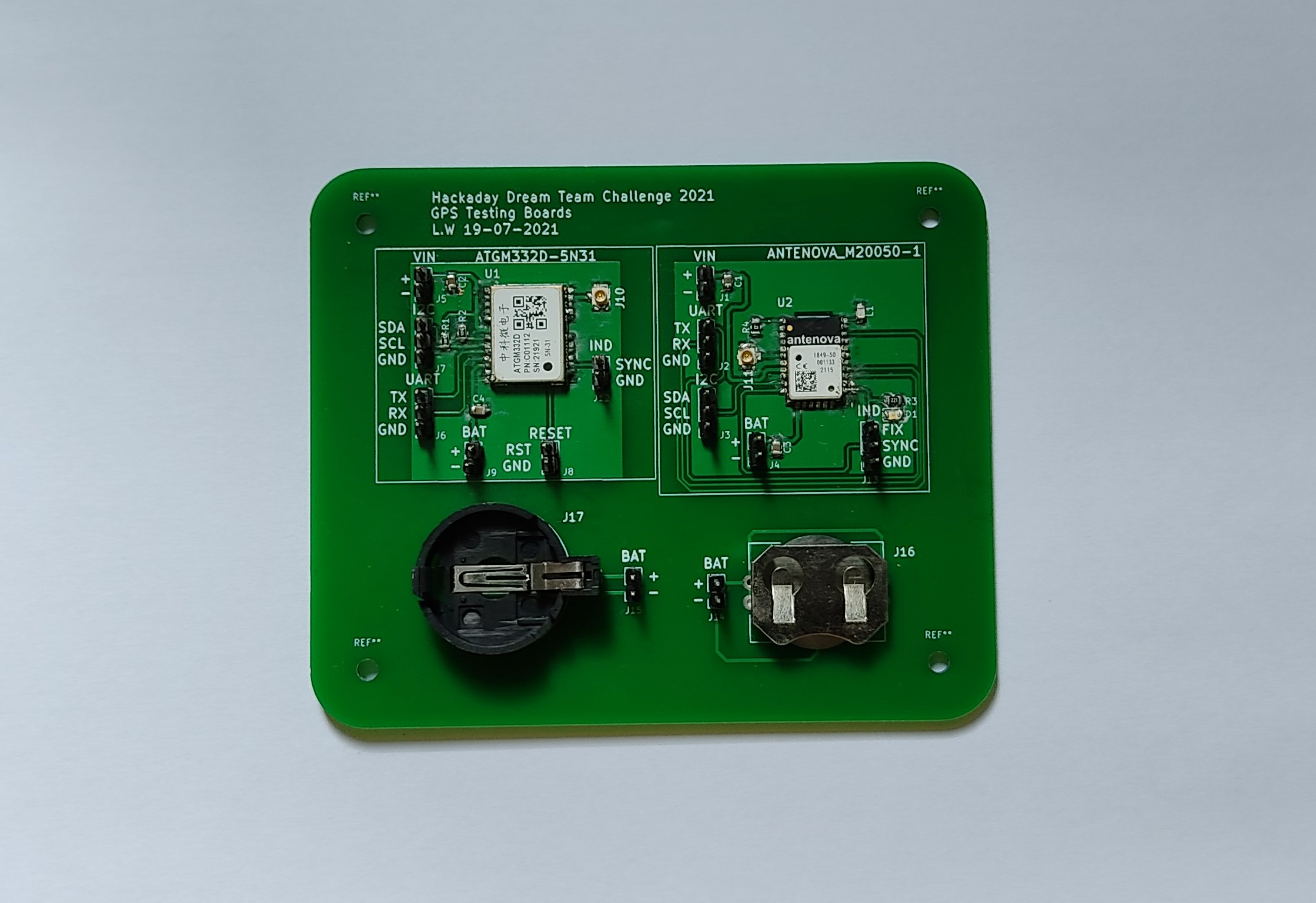
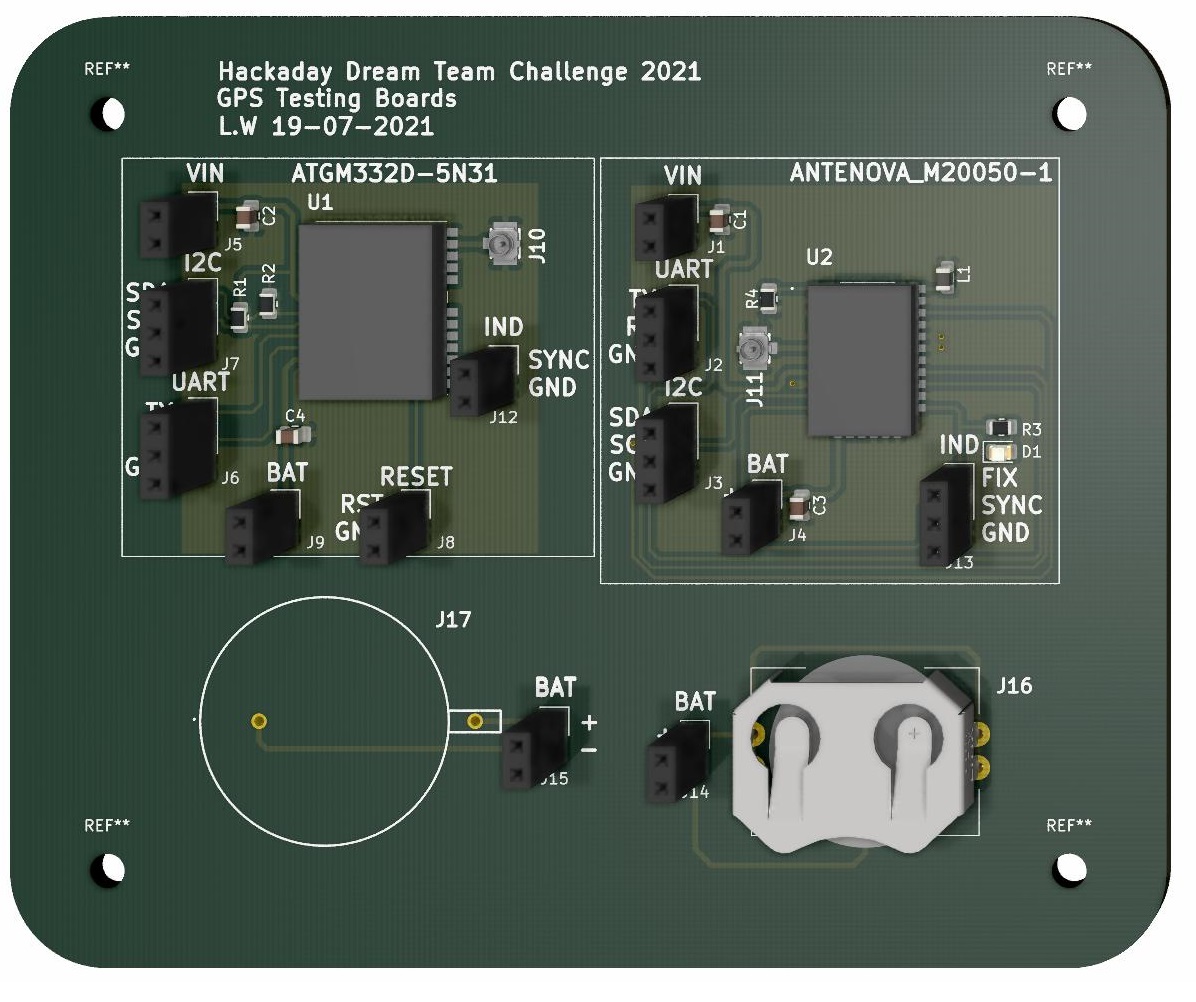
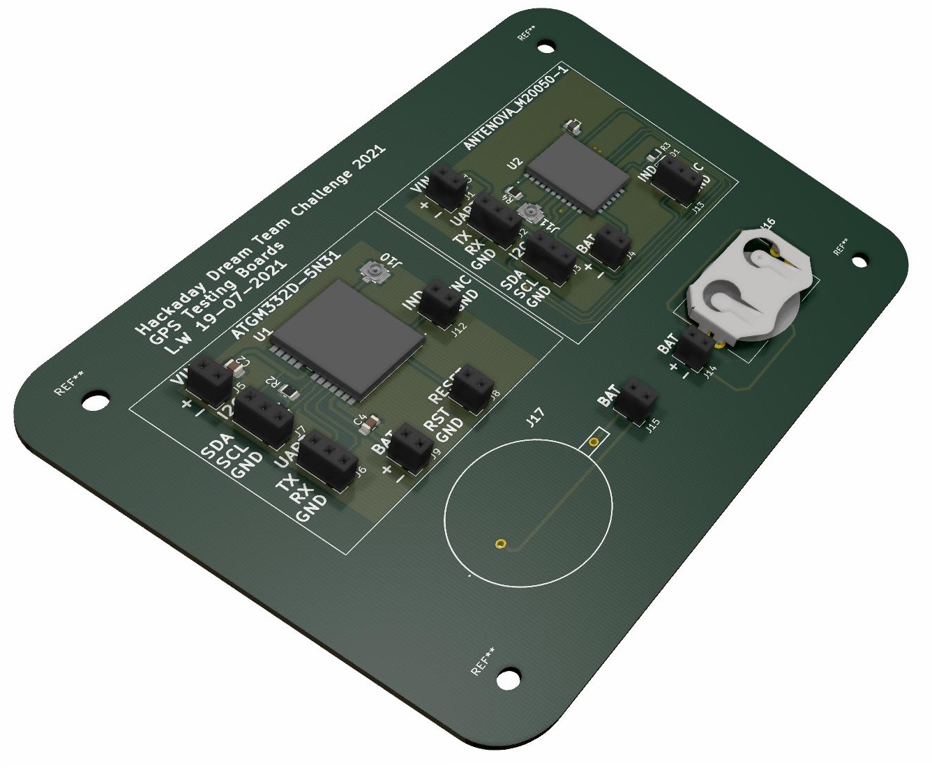
A KiCad breakout board for evaluating two GPS modules side by side — the ANTENOVA M20050-1 and the ATGM332D-5N31 — plus two footprints for 20 mm coin‑cell holders to keep the module's backup RAM / almanac powered for a warm start.
This is one of the breakout boards made for the EJA "Intelligent Popup Buoy" project (2021 Hackaday Dream Team). Each candidate part for the EJA M board was first tried on a small dedicated PCB. Both GPS modules speak plain NMEA over UART and are wired to identical header pinouts here, so the same ESP32 firmware runs against either one. The ATGM332D-5N31 was the module chosen for EJA M.
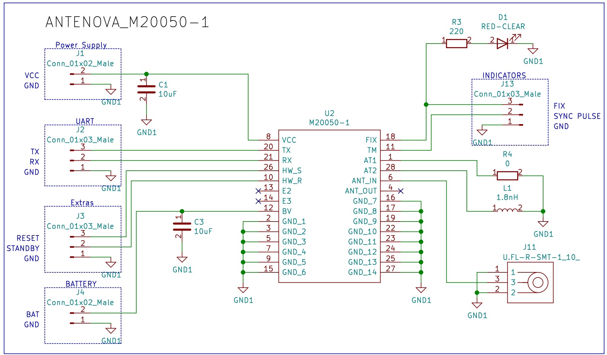
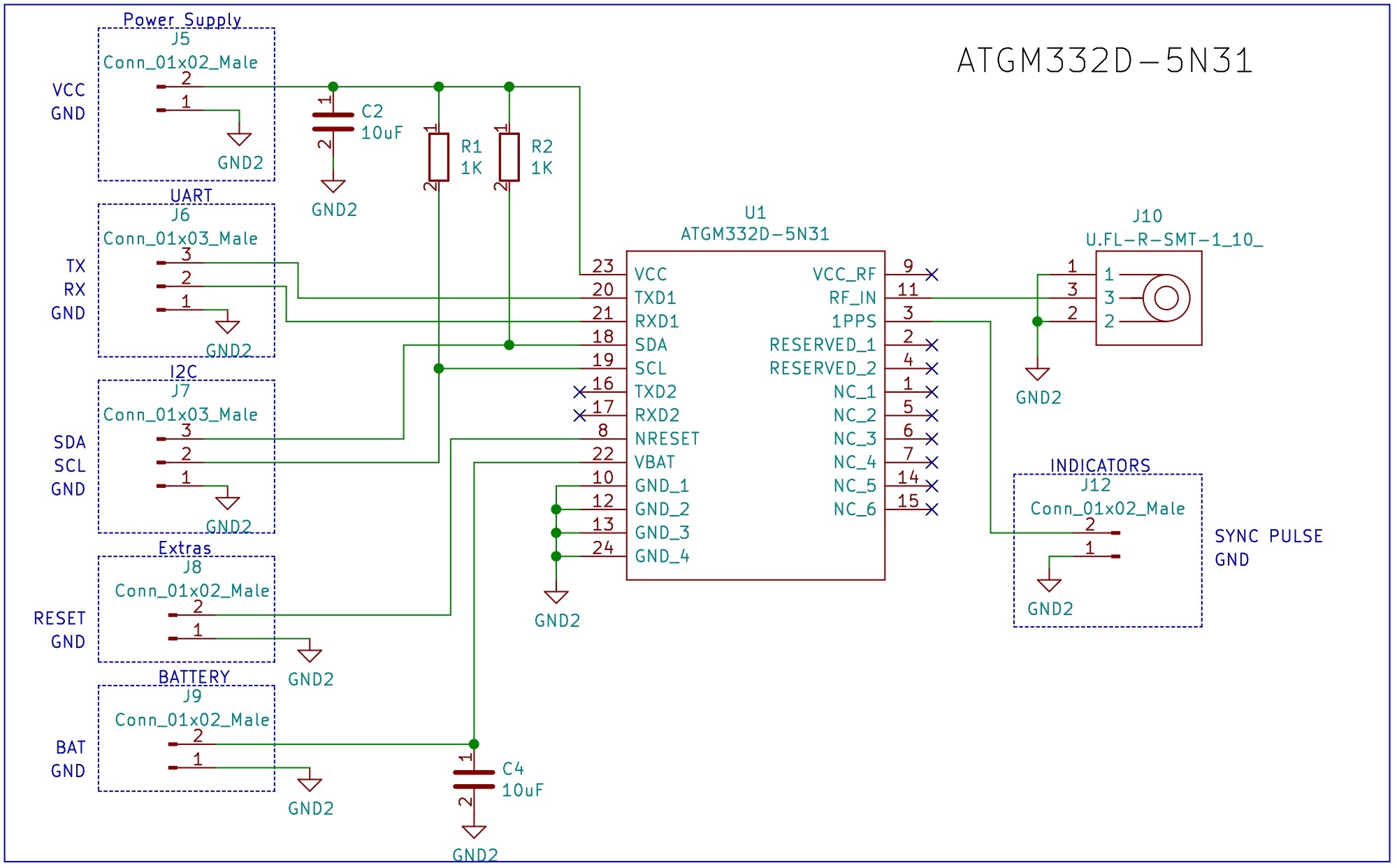
Each module has a decoupling capacitor, a U.FL connector for an external active
antenna, a coin‑cell backup input, and UART / I2C / IND (fix indicator) broken
out to headers.
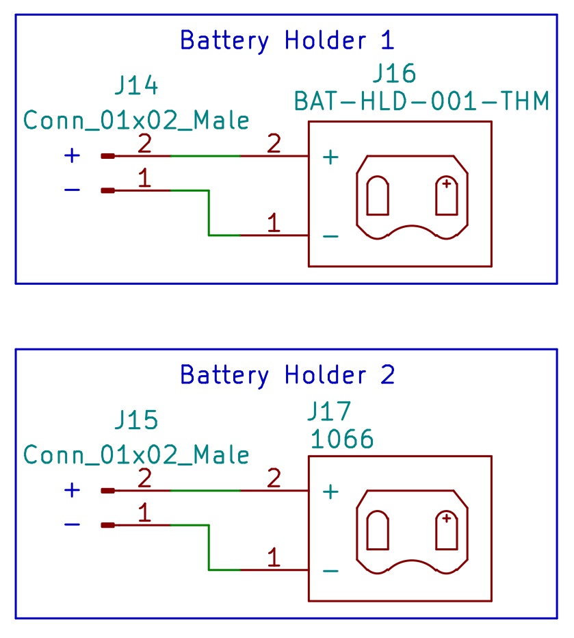
Two 20 mm coin‑cell holder footprints (a Linx BAT-HLD-001 retainer and a Keystone 1066 open holder) so the mechanically better one can be picked for the buoy.
A machine-readable BOM is in gps-testing-board/gps-testing-board.csv.
Firmware/ has an Arduino sketch for each module (esp32_atgm332d/ and
esp32_antenova_m20050/). Both are the same code with a different banner; only one
module is exercised at a time.
Serial2 runs at 9600 baud on GPIO16 (RX) / GPIO17 (TX), wired
to the module's UART header.FuGPS library parses the NMEA stream. The
sketch asks the module for RMC + GGA sentences
(FUGPS_PMTK_API_SET_NMEA_OUTPUT_RMCGGA).google.com/maps link with the current latitude / longitude;
if the module goes quiet for ~10 s it prints a "not responding" warning.
Wire the module header to the ESP32 (VIN→3V3, GND→GND,
TX→GPIO16, RX→GPIO17), fit an active antenna on the U.FL connector,
open the matching sketch in the Arduino IDE (ESP32 board support + the FuGPS library
installed) and watch the serial monitor at 115200 baud. A first fix outdoors takes a
few minutes cold, seconds warm with the backup cell fitted.
README.md
LICENSE                              Apache 2.0
Schematic v1.0.pdf                   exported schematic
Images/                              schematics, 3D renders, board photos
Firmware/
  esp32_atgm332d/                    Arduino sketch, ATGM332D-5N31
  esp32_antenova_m20050/             Arduino sketch, ANTENOVA M20050-1
gps-testing-board/                   KiCad project
  gps-testing-board.pro/.sch/.kicad_pcb
  gps-testing-board.csv              BOM
  Symbols/ Footprints/ 3D/           project-local libraries
  Gerber/                            fabrication output
Exports/ STEP model| Qty | Value | Footprint | References |
|---|---|---|---|
| 8 | Conn_01x02_Male | Connector_PinSocket_2.54mm:PinSocket_1x02_P2.54mm_Vertical | J1, J4, J5, J8, J9, J12, J14, J15 |
| 5 | Conn_01x03_Male | Connector_PinSocket_2.54mm:PinSocket_1x03_P2.54mm_Vertical | J2, J3, J6, J7, J13 |
| 4 | 10uF | Capacitor_SMD:C_0805_2012Metric | C1, C2, C3, C4 |
| 2 | 1K | Resistor_SMD:R_0805_2012Metric | R1, R2 |
| 2 | U.FL-R-SMT-1_10_ | U.FL-R-SMT-1(10):U.FL-R-SMT-1_10_ | J10, J11 |
| 1 | 0 | Resistor_SMD:R_0805_2012Metric | R4 |
| 1 | 1.8nH | Inductor_SMD:L_0805_2012Metric | L1 |
| 1 | 1066 | BAT-1066:BAT-1066 | J17 |
| 1 | 220 | Resistor_SMD:R_0805_2012Metric | R3 |
| 1 | ATGM332D-5N31 | ATGM332D-5N31:ATGM332D5N31 | U1 |
| 1 | BAT-HLD-001-THM | BAT-HLD-001-THM:BATHLD001THM | J16 |
| 1 | M20050-1 | M20050-1:M200501 | U2 |
| 1 | RED-CLEAR | LED_SMD:LED_0805_2012Metric | D1 |
The 29 most common of 33 parts.
It measures 107 × 88 mm and has 2 copper layers, 1.6 mm thick.
33 parts, built around the ATGM332D-5N31, M20050-1 and BAT-HLD-001-THM. The full list of its parts is on this page, with links to each part's symbol and footprint where PCBKit's library has them.
From the leonardoward/gps-development-boards repository on GitHub, at the commit this page was made from: the board is gps-testing-board/gps-testing-board.kicad_pcb. PCBKit opens the board in the browser, with nothing to install.
Its repository publishes it under the Apache-2.0 licence: you may reuse it on that licence's terms (keep the author's notice, and for a copyleft licence share your changes alike).

YeetTheAnson/RFly-One
Offline general aviation proximity awareness system with support for ADS-B, FLARM AIR V7, OGNTP and FANET+


alxlab-zone66x/cr2032_toaster
CR2032 to 1/2AA converter to use in various old Macintosh computers that used 1/2AA batteries as the PRAM battery.

uw-x/clearbuds-hw
Errata: The design contains some errors that can be addressed in future revisions. The errors do not affect function, but do affect robustness. 1. Add 0.1uF decoupling capacitor to PDM mic (ICS-41350) Vcc. 2.


