4 layers111 × 110 mm
Complex vco ranged
lennartquerter/euro-rack-synth
Lenimal Github for DIY for a Eurorack Synth
234 parts13

 lennartquerter/euro-rack-synth13
Lenimal Github for DIY for a Eurorack Synth
Folder sample player is an open-source printed circuit board by lennartquerter, from the lennartquerter/euro-rack-synth repository on GitHub. It is a 2-layer board of 60 × 110 mm with 191 parts on 153 nets, routed with 5 tracks and 0 vias.
It is built around the MCP6002-I/P, TL072 and 74HC595, with the 1N4148WS, MMBT3904 and MMBT3906 among its other parts. Its parts include 80 resistors, 29 connectors, 28 diodes, 22 capacitors and 21 transistors. It belongs with the audio and music boards of this library.


tags: lenimal, eurorack, synthesizer, diy, electronics, music
This is a collection of notes and resources for building a Eurorack synth. I'm not an expert, but I'm learning as I go and I'm happy to share what I've learned.
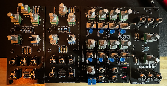
(First version without panels)
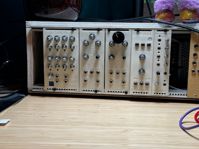
(First version with 3D printed panels, I'm still missing knobs)
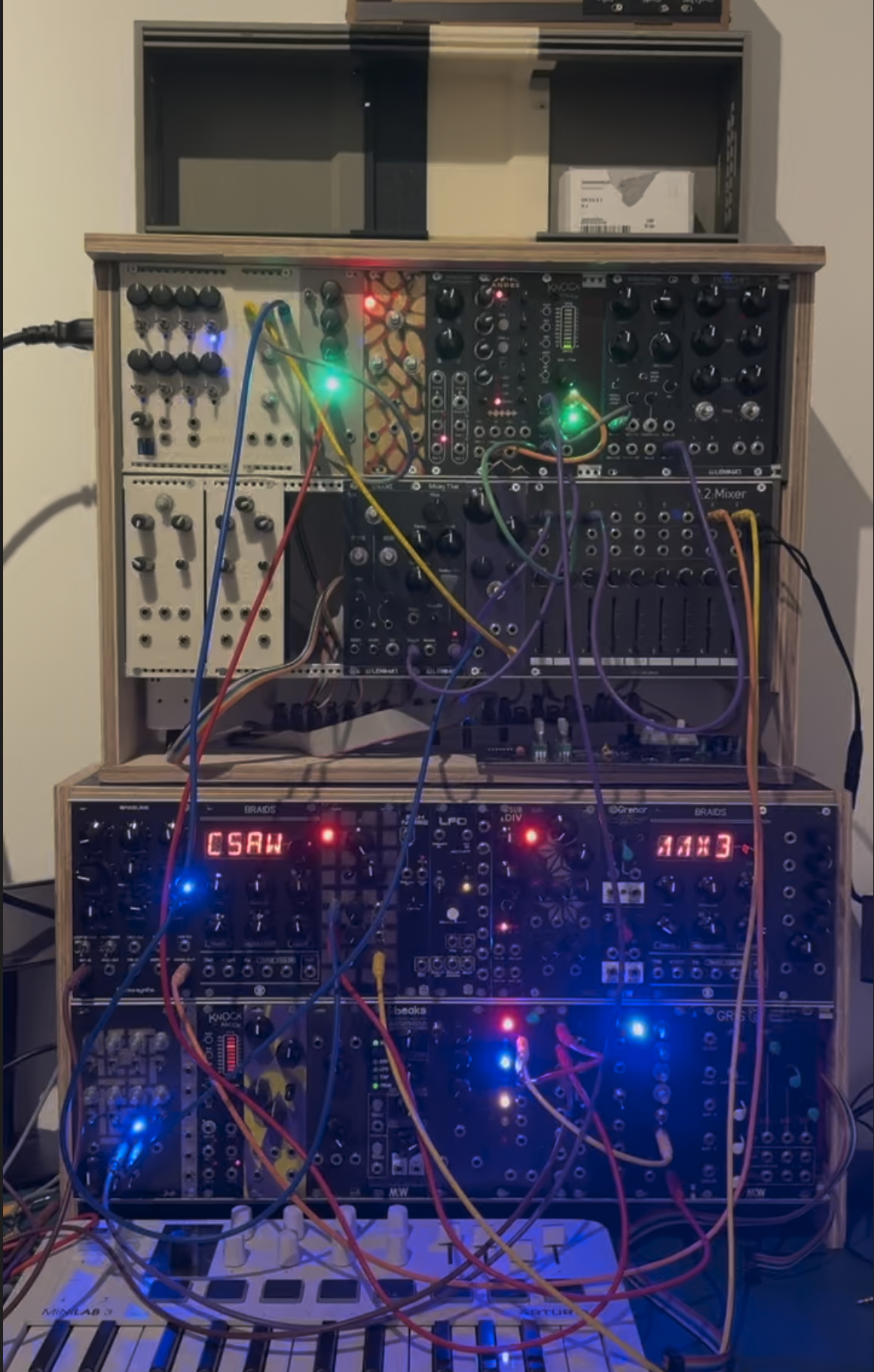
I am not responsible for any damage to any of your modules. The modules within this repository have been tested and built by myself and used only with the other modules in this system.
There is a chance they work well with other off-the-shelf modules, but I do not own any, so I can not test it out. If you proceed to copy or use any file within this repository, you are doing this at your own risk.
These modules are also not perfect 1v/oct or temperature controlled. This project should be seen as a fun hobby project and not as professional advice on how to build synthesisers.
There are tags on the commit that was ordered (for the exact gerber files)
If there are issues, they will be reported in the README for each module.
| Type | Module | Version | Status | Tested | Issues? | Panel available |
|---|---|---|---|---|---|---|
| VCO | Vixen [MKI] | 2 | Built | yes | No | Yes (3D print) |
| VCO | 3340 | 1 | Built | Yes | No | Yes (3D print) |
| LFO | XOF | 1 | Built | Yes | No | Yes (3D print) |
| VCA | Sparkle [MKI] | 2 | Built | Yes | No | Yes (3D print) |
| SEQ | Sensei [Baby 8] | 2 | Built | yes | No | Yes (3D print) |
| EG | Scribble [MKI] | 2 | Built | yes | No | Yes (3D print) |
| EG | 7555 [Fastest Envelope] | 1 | Built | yes | No | Yes (3D print) |
| Filter | 3320 | 1 | Built | Yes | No | Yes (3D print) |
| Filter | Low Orbit [MKI] | 1 | Built | yes | No | Yes (3D print) |
| Mixer | Distorted Daisy [MKI] | 2 | Built | yes | No | Yes (3D print) |
| Drums | Muay Thai (Kick) [MKI] | 1 | Built | Yes | No | Yes (Gerber) |
| Utility | Wavefolder (SuperNova) | 1 | built | Yes | Minor | Yes (Gerber) |
| Utility | Passive Mult | 1 | Built | Yes | No | Yes (3D print) |
| Utility | Active Mult | 1 | Built | Yes | No | Yes (3D print) |
| Utility | Chrono Divider | 1 | Built | yes | No | Yes (3D print) |
| Utility | Euro ProtoType Helper | 1 | Built | yes | No | No |
| Utility | Cable tester | 1 | Built | Yes | No | No |
| Drums | Clap/Snare | 1 | NotWorking | yes | ? | Yes (Gerber) |
| Utility | Midi-2-cv (Midas) | 2 | Built | yes | No | Yes (Gerber) |
| FX | Delay (PT-chip) | 2 | Built | Yes | No | Yes (Gerber) |
| FX | Storm [Clouds] | 2 | Built | yes | Minor | Yes (Gerber) |
Since young, I have always been interested in 2 things: Electronics & Music. I have played many instruments over the years (drums, guitar, and a bit of piano). When I was a teenager, I got into electronic music production. I DJ'ed (as Lenimal) for about 10 years in and around Belgium.
I moved into software engineering after my studies in Film. Not having a computer science or electronics degree, I always felt that I needed to explore the connection with the hardware on which my software ran.
I started following a YouTube series by Ben Eater, showing how to build an 8-bit computer on breadboards. I got pretty far until my cat, being the cat he is, decided that the computer would look better on the ground, destroying most of the connections. The motivation to continue was lost after seeing the work it would take to repair it.
I learned quite a lot about electronics during that process! While visiting family in the States, I got the opportunity to visit the MOOG factory in Ashville, NC. I didn't buy a MOOG (sadly enough), but I got the MFOS book on how to build an analog synth.
After immersing myself in the MFOS book, I was filled with a sense of determination. I read the book cover to cover at least four times, absorbing every detail. It was then that I made a firm decision-I was going to build my own synthesizer!
I started watching more in-depth tutorials on YouTube and came across Moritz Klein's channel. He explains the process in great detail and I could follow along at home. (Thank you, Moritz!)
I still had ample chips, resistors, and capacitors from my previous 8-bit computer build, so I started looking into the more specialized equipment I needed. It was clear very soon that I needed a reasonable Oscilloscope and some other things (described below).
Once I had collected all the needed items, I made a goal. In 2024, I would build a modular synth from scratch. It took me 3-4 months to get the first 5 modules:
Of course, they didn't turn out perfect. When I ordered the PCBs and started soldering, I found many issues. Some on the schematic (like I connected the wrong inputs on the op-amp on the EG) and others on the PCB (my first attempt at an SPDT switch footprint didn't fit my switches at all).
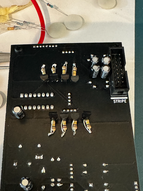
(example of a hack on the V1 boards because I forgot the resistors)
As I'm learning, I will keep updating the modules in this repository. I hope it inspires and helps others create awesome modules & start their adventure into DIY Synths!
As my creativity ends with designing PCB's, I call upon my (very beautiful) wife to name the modules, this is why they might sound like the name of unicorns.
I didn't have much electronic equipment, so I started saving and purchasing as I got the money:
I already had most of the other small tools, but here is a list of my most used tools:
The next step was to start sourcing components, because I did not want to just order kits.
I started by watching lots of YouTube and getting schematics from the internet. That gave me a good idea of the main things I would need. Here are the most used components I have. The quantity is just a guideline for how many I got to get started.
Most of the items I got in bulk while travelling in Asia. I kept space in my suitcase for these components as I could get them pretty cheap there. I didn't have any problems with flying when checking them in, and no issues with customs. (this is not a promise that you will not have problems, always read guidelines and regulations of the country you are flying from/to)
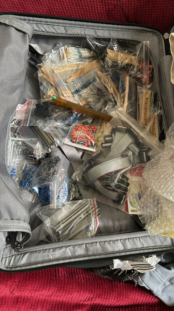
(Suitcase coming back from Shanghai)
I started with a big set of lots of different values to start with, and ordered in bulk when I needed them. Here is the list of my most used resistor values:
I have been looking for cheap (but good) ones that fit on PCB's vertically for a long time. The best I can found are the ALPHA 9mm (I buy them on thonk.co.uk). You can find some on digiKey, but the ALPHA's are my recomendation. I bought some with a D-shaft, and others just as a long shaft.
It's also good to have some of every value. I got a box of electrolytic, ceramic and film
For the film capacitor's I try to use WIMA Caps
... you might want to buy just a set of these
There are some general NPN and PNP transistors you can get, I mainly got some variety that I found on videos and blogs:
I use kiCad, open-source software to design all my schematics. It's pretty easy to get a hang of it and also has a built in PCB editor. You can also design custom footprints for components they don't have in their (pretty big) library. I have included some of my footprints/symbols in this repo.
For my first PCB, I had some testing points and that made it easier to debug. I forgot them for all the other ones and had a really bad time. I had to keep prodding resistor legs to understand what was going on. Always add testing points to your schematic & PCB.
Always measure 20 times when creating a footprint. It's really annoying when you have ordered your new PCB and the component just does not fit. I tried to make a SPDT switch footprint, and they just did not fit well.
Make sure when you are giving the pins a number, the correspond to the correct number on the whole. I had the issue with my SPDT switch, that they just didn't work. I got the holes mixed up and ended with the wrong pin out.
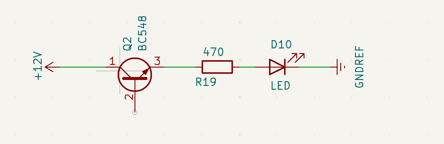
When using an LED, never connect it directly to an IC to drive it. Always use a transistor to drive the LED. This is important because you don't want to burn your IC because there is too much current flowing over your LED.
If you are following my schematics, you will see I use header/socket pins to connect my boards. I first started with the 2.00mm pins. I could not easily find tall sockets, so I ended having to always stack 2 on top of each other, this was not super stable in the end, and I had to solder all the cap's to the back of the board because I didn't want to use 3 stacked socket pins.
I currently use the more standard 2.56mm pins.
Make sure you place 4 mounting holes on your board, and that they match the coordinates of the top board. I got simple 3mm & 2mm spacers from nylon.
I have a 3D printer accessible at the office, so I use it to build and prototype the designs. At some point I might turn to a professional milling company but for now, it works well. I use Fusion 360 for the designs (there is a free non-commercial license!).
PCBs are ordered, not yet built or tested.
| Type | Module | Version | Status | Tested |
|---|---|---|---|---|
| Utility | Magician / Rota Fortunae (Quantizer) | 2 | Ordered | No |
| Utility | Clockfall (Master Clock) | 1 | Ordered | No |
| Utility | Numica Core (Precision Adder) | 1 | Ordered | No |
| Utility | Xpander (Dual Compressor) | 1 | Ordered | No |
| VCA | MLK (Quad VCA) | 1 | Ordered | No |
| Drums | Basari [Clone] | 1 | Ordered | No |
| Clone | The Wheel / The Pattern [Plaits] | 1 | Ordered | No |
| Utility | Bus Board | 1 | Ordered | No |
The following modules are still under active development. They are not yet ready for production usage.
| Type | Module | Version | Status | Tested |
|---|---|---|---|---|
| Drums | Snare / Clap | 2 | Concept | No |
| Drums | Coliseum (Cymbals & Hats) | 1 | Concept | No |
| Drums | Toms / Subkick | 1 | Concept | No |
| Drums | Bazaar (Percussion) | 1 | Concept | No |
| Utility | SD card folder Sampler | 1 | Concept | No |
| Utility | Conductor | 1 | Concept | No |
| Mixer | 9-Channel Stereo Mixer | 1 | Concept | No |
| Clone | Cat's Eye [Marbles] | 1 | Concept | No |
| Type | Module | Version | Status | Tested |
|---|---|---|---|---|
| Utility | Noise Module | 1 | Concept | No |
| Utility | AND/OR | 1 | Concept | No |
| Utility | Math? | 1 | Concept | No |
| Utility | 1v/oct tuner | 1 | Concept | No |
| FX | Delay (DBB) | 1 | Concept | No |
| FX | Reverb (Spring) | 1 | Concept | No |
| FX | Sample&Hold | 1 | Concept | No |
| Type | Module | Version | Status | Tested | Issues? |
|---|---|---|---|---|---|
| VCO | Vixen | 1 | Built | Yes | Minor |
| VCA | Sparkle | 1 | Built | Yes | No |
| SEQ | Sensei | 1 | Built | Yes | Minor |
| EG | Scribble | 1 | Built | Yes | Yes |
| Mixer | Distorted Daisy | 1 | Built | yes | No |
| Utility | Midi-2-cv (Midas) | 1 | Built | yes | yes |
| Drums | Clap/Snare | 1 | Built | yes | yes |
| FX | Delay (PT-chip) | 1 | Built | Yes | yes |
| FX | Clouds Clone / Digital FX | 1 | Built | yes | yes |
| Qty | Value | Footprint | References |
|---|---|---|---|
| 38 | 100K | Resistor_SMD:R_0805_2012Metric_Pad1.20x1.40mm_HandSolder | R100, R101, R103, R105, R106, R107, R109, R111, R112, R113, R115, R117, R118, R120, R121, R123 +22 |
| 18 | 10K | Resistor_SMD:R_0805_2012Metric_Pad1.20x1.40mm_HandSolder | R72, R78, R84, R102, R108, R114, R119, R122, R125, R126, R129, R131, R132, R143, R144, R146 +2 |
| 18 | 1N4148WS | Diode_SMD:D_SOD-323_HandSoldering | D10, D11, D13, D14, D16, D17, D19, D20, D22, D23, D25, D26, D28, D29, D31, D32 +2 |
| 18 | MMBT3904 | Package_TO_SOT_SMD:SOT-23_Handsoldering | Q1, Q2, Q3, Q4, Q5, Q6, Q7, Q10, Q11, Q12, Q13, Q14, Q15, Q16, Q17, Q18 +2 |
| 10 | 10nF | Capacitor_SMD:C_0805_2012Metric_Pad1.18x1.45mm_HandSolder | C65, C66, C67, C68, C69, C70, C71, C72, C73, C74 |
| 9 | 100nF | Capacitor_SMD:C_0805_2012Metric_Pad1.18x1.45mm_HandSolder | C2, C5, C10, C11, C14, C15, C75, C76, C77 |
| 8 | 220R | Resistor_SMD:R_0805_2012Metric_Pad1.20x1.40mm_HandSolder | R133, R135, R137, R139, R140, R141, R142, R145 |
| 8 | 4K7 | Resistor_SMD:R_0805_2012Metric_Pad1.20x1.40mm_HandSolder | R74, R80, R86, R92, R98, R104, R110, R116 |
| 8 | GATE_IN | Synth:Jack_3.5mm_QingPu_WQP-PJ398SM_Vertical_CircularHoles | J14, J15, J16, J17, J18, J19, J20, J21 |
| 8 | LED | Synth:LED_D3.0mm | D9, D12, D15, D18, D21, D24, D27, D30 |
| 8 | OUTPUT | Synth:Jack_3.5mm_QingPu_WQP-PJ398SM_Vertical_CircularHoles | J2, J3, J4, J5, J6, J7, J8, J9 |
| 3 | 1K | Resistor_SMD:R_0805_2012Metric_Pad1.20x1.40mm_HandSolder | R134, R136, R138 |
| 3 | MMBT3906 | Package_TO_SOT_SMD:SOT-23 | Q19, Q20, Q21 |
| 2 | 10R | Resistor_SMD:R_0805_2012Metric_Pad1.20x1.40mm_HandSolder | R2, R3 |
| 2 | 1N5819 | Diode_SMD:D_SOD-123 | D1, D2 |
| 2 | 30k | Resistor_SMD:R_0805_2012Metric_Pad1.20x1.40mm_HandSolder | R124, R130 |
| 2 | 47uF | Capacitor_THT:CP_Radial_D5.0mm_P2.50mm | C8, C9 |
| 2 | 74HC595 | Synth:SOIC-16 | U12, U13 |
| 2 | INPUT | Synth:Jack_3.5mm_QingPu_WQP-PJ398SM_Vertical_CircularHoles | J22, J23 |
| 1 | +12V | TestPoint:TestPoint_Plated_Hole_D2.0mm | TP2 |
| 1 | +3.3V | TestPoint:TestPoint_Plated_Hole_D2.0mm | TP1 |
| 1 | -12V | TestPoint:TestPoint_Plated_Hole_D2.0mm | TP4 |
| 1 | 10uF | Capacitor_THT:CP_Radial_D4.0mm_P2.00mm | C1 |
| 1 | 33K | Resistor_SMD:R_0805_2012Metric_Pad1.20x1.40mm_HandSolder | R128 |
| 1 | 3x7-segment_display | Synth:3x7-segment-display_SP410361N | U1 |
| 1 | CV_INPUT | Synth:Jack_3.5mm_QingPu_WQP-PJ398SM_Vertical_CircularHoles | J24 |
| 1 | Conn_02x05_PWR_Eurorack | Synth:IDC-Header_2x05_P2.54mm_Vertical | H1 |
| 1 | GATE_INPUT_1 | Connector_PinSocket_2.54mm:PinSocket_1x06_P2.54mm_Vertical | J28 |
| 1 | GATE_INPUT_2 | Connector_PinSocket_2.54mm:PinSocket_1x06_P2.54mm_Vertical | J29 |
| 1 | GND | TestPoint:TestPoint_Plated_Hole_D2.0mm | TP3 |
| 1 | INPUT_A | Connector_PinSocket_2.54mm:PinSocket_1x06_P2.54mm_Vertical | J1 |
| 1 | INPUT_B | Connector_PinSocket_2.54mm:PinSocket_1x05_P2.54mm_Vertical | J11 |
| 1 | LED_DRIVER | Connector_PinSocket_2.54mm:PinSocket_1x05_P2.54mm_Vertical | J13 |
| 1 | LFO_INPUT | Synth:Jack_3.5mm_QingPu_WQP-PJ398SM_Vertical_CircularHoles | J25 |
| 1 | MCP6002 | Synth:SOIC-8 | U4 |
| 1 | MODEL_SELECT | KEM:RotaryEncoder_Alps_EC11E_Vertical | SW1 |
| 1 | Micro_SD_Card | Synth:yamaichi_PJS008U | J26 |
| 1 | OUTPUT_1 | Connector_PinSocket_2.54mm:PinSocket_1x06_P2.54mm_Vertical | J10 |
| 1 | OUTPUT_2 | Connector_PinSocket_2.54mm:PinSocket_1x06_P2.54mm_Vertical | J12 |
| 1 | SD_CONNECTOR | Connector_PinSocket_2.54mm:PinSocket_1x08_P2.54mm_Vertical | J27 |
| 1 | TL072 | Synth:SOIC-8 | U5 |
lennartquerter/euro-rack-synth
Lenimal Github for DIY for a Eurorack Synth


lennartquerter/euro-rack-synth
Lenimal Github for DIY for a Eurorack Synth


mzuelch/CATs-Eurosynth
Analog Synth Eurorack Modules

Emute-Lab-Instruments/Myriad
Sources for Emute Lab Instruments Myriad eurorack module


StudioKAT/VintageDualVCA
If nothing is patched into OUT1, the signal from CH1 is automatically mixed into OUT2.


It measures 60 × 110 mm and has 2 copper layers, 1.6 mm thick.
191 parts, built around the MCP6002-I/P, TL072, 74HC595 and 1N4148WS. The full list of its parts is on this page, with links to each part's symbol and footprint where PCBKit's library has them.
From the lennartquerter/euro-rack-synth repository on GitHub, at the commit this page was made from: the board is modules/utility/10-folder-sampler/kiCad/control/_restore_backup_2026-10-14T20-35-09-742/folder-sample-player.kicad_pcb. PCBKit opens the board in the browser, with nothing to install.
Its repository states no licence, so its author keeps all rights: ask lennartquerter before reusing the design.