
2 layers21.1 × 26.9 mm

 Lenart12/etera-uart-bridge2
Expander board for driving valve motors, relays and measuring tempature
Optocupler is an open-source printed circuit board by Lenart12, from the Lenart12/etera-uart-bridge repository on GitHub. It is a 2-layer board of 100 × 100 mm with 63 parts on 69 nets, routed with 320 tracks and 6 vias.
It is built around the BS170. Its parts include 20 resistors, 11 capacitors, 10 diodes, 9 connectors and 8 ICs. It belongs with the audio and music and home automation and IoT boards and the AVR (ATmega, ATtiny) boards of this library.
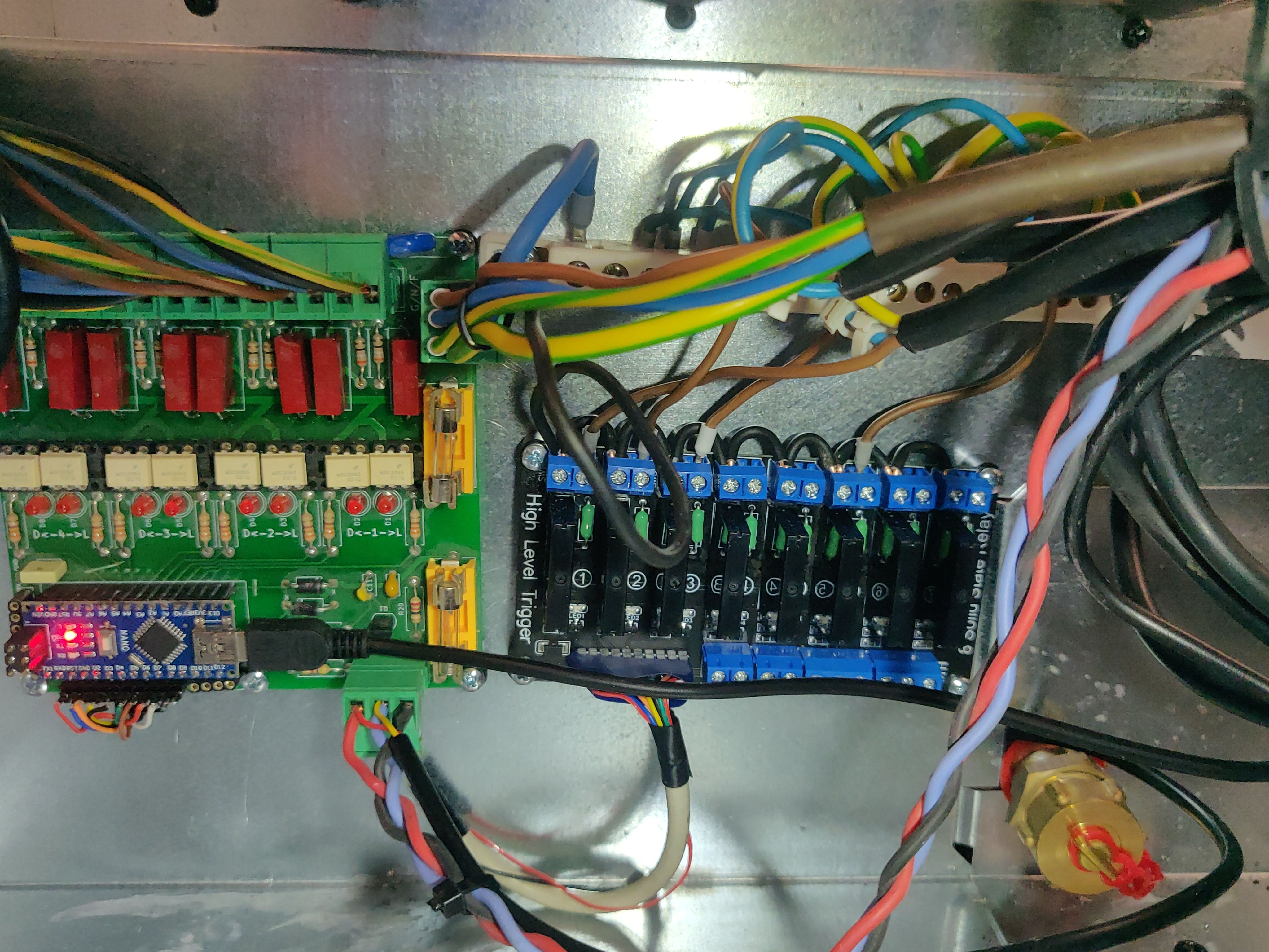
This project is an expander board designed to provide control for valve motors, eight relays, and the ability to measure multiple temperature sensors using the one-wire protocol. The board is implemented using KiCad PCB design software and the PCB files can be found in the pcb folder. The firmware for the board is developed using PlatformIO and can be found in the pio-eub-firmware folder. Additionally, a Python library for interfacing with the expander board is available in the pyetera-uart-bridge folder.
More information about the expander board, including usage instructions and examples, can be found in the pyetera-uart-bridge/README.md file.
The expander board is designed to provide versatile control capabilities for various applications. It features 8 GPIO pins that can be utilized for controlling relays or other general-purpose tasks. Additionally, the board is equipped with the ability to control 4 motors, incorporating optocouplers to ensure protection and isolation of the motor control circuits.
For temperature monitoring, the board supports one-wire temperature sensors. These sensors are enhanced with an active pull-up mechanism to ensure reliable communication over long distances. Furthermore, the board includes a FET driver to improve the slew rate, which helps in reducing electromagnetic interference and improving signal integrity over long wire distances. For this purpose the standard Arduino OneWire library was modified into OneWireFet which can support mastering the 1-wire bus with two uC pins.
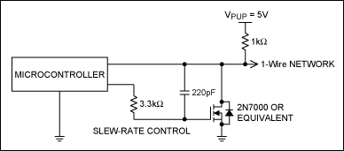
For long line applications, modifications are necessary. Appendix A shows a variant of the microprocessor port-pin attachments, i e., a FET driver with slew-rate control and a 1kΩ pullup resistor. A radius of up to 200m and a weight of up to 200m can be reliably supported using this interface.
For more detailed guidelines on setting up reliable long-line one-wire networks, you can refer to this technical article.


| Qty | Value | Footprint | References |
|---|---|---|---|
| 20 | R | Resistor_THT:R_Axial_DIN0411_L9.9mm_D3.6mm_P12.70mm_Horizontal | R1, R2, R3, R4, R5, R10, R11, R12, R13, R14, R15, R16, R17, R18, R19, R20 +4 |
| 8 | C | Capacitor_THT:C_Axial_L17.0mm_D6.5mm_P20.00mm_Horizontal | C1, C2, C3, C4, C5, C6, C7, C8 |
| 8 | LED | LED_THT:LED_D5.0mm | D1, D2, D3, D4, D5, D6, D7, D8 |
| 8 | NSL-32 | optocupler:DIP-5-6_W7.62mm_LongPads | U1, U2, U3, U4, U5, U6, U7, U8 |
| 4 | Conn_01x04_Male | Connector_Phoenix_MSTB:PhoenixContact_MSTBVA_2,5_4-G_1x04_P5.00mm_Vertical | J4, J5, J6, J7 |
| 3 | C | Capacitor_THT:C_Disc_D4.7mm_W2.5mm_P5.00mm | C9, C10, C11 |
| 2 | Conn_01x03_Female | Connector_JST:JST_NV_B03P-NV_1x03_P5.00mm_Vertical | J3, J9 |
| 2 | D_Shockley | Diode_THT:D_A-405_P10.16mm_Horizontal | D9, D10 |
| 2 | Fuse | Fuse:Fuseholder_Cylinder-5x20mm_Stelvio-Kontek_PTF78_Horizontal_Open | F1, F2 |
| 1 | Arduino_Nano_v3.x | Module:Arduino_Nano | A1 |
| 1 | BS170 | Package_TO_SOT_THT:TO-92_Inline | Q1 |
| 1 | Conn_01x04_Female | Connector_PinSocket_2.54mm:PinSocket_1x04_P2.54mm_Vertical | J8 |
| 1 | Conn_01x05_Female | Connector_PinSocket_2.54mm:PinSocket_1x05_P2.54mm_Vertical | J2 |
| 1 | Conn_01x10_Female | Connector_PinSocket_2.54mm:PinSocket_1x10_P2.54mm_Vertical | J1 |
| 1 | Varistor | Varistor:RV_Disc_D15.5mm_W4mm_P7.5mm | RV1 |


pablozg/freeds
Derivador de energía solar excedente creado por Pablo Zerón, Diseño PCB por Amcalo, Tester original por Aeizoon, Wiki por Zoilo Mora

PhysicsDptAngers/polyUAnalog
Open source, analog and polyphonic synthesizer


DRWJSCHMIDT/T41
This is the repository for the officially released V10, V11, and V12 versions of the T41 Software Defined Transceiver hardware and kits.

sffubs/dactyl_manuform_gimbal
Instrutions and designs for building the dactyl-manuform-gimbal keyboard
It measures 100 × 100 mm and has 2 copper layers, 1.6 mm thick.
63 parts, built around the BS170. The full list of its parts is on this page, with links to each part's symbol and footprint where PCBKit's library has them.
From the Lenart12/etera-uart-bridge repository on GitHub, at the commit this page was made from: the board is pcb/optocupler.kicad_pcb. PCBKit opens the board in the browser, with nothing to install.
Its repository states no licence, so its author keeps all rights: ask Lenart12 before reusing the design.