


2 layers128 × 95 mm

 lelandbatey/clock-module1
Kicad designs for the clock module of Ben Eater's home-made CPU
Clock module--100mmX100mm is an open-source printed circuit board by lelandbatey, from the lelandbatey/clock-module repository on GitHub. It is a 2-layer board of 56 × 100 mm with 35 parts on 26 nets, routed with 193 tracks and 21 vias.
It is built around the LM555N, 74LS04PC and 74LS32SC. Its parts include 10 resistors, 8 connectors, 6 ICs, 5 capacitors and 4 diodes. It belongs with the lEDs and displays boards of this library.
This repo contains PCB designs for the first component of Ben Eater's educational 8-bit CPU, the clock module. You can watch Mr. Eaters fantastic series on designing and building this CPU on his Youtube channel.
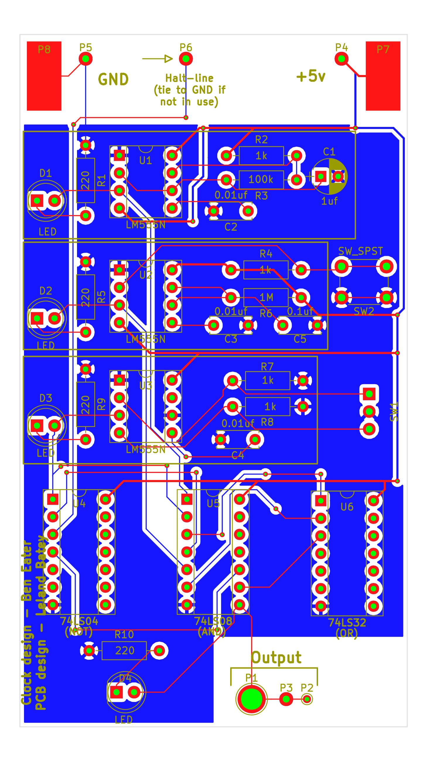
| Qty | Value | Footprint | References |
|---|---|---|---|
| 4 | 1k | Resistors_THT:R_Axial_DIN0207_L6.3mm_D2.5mm_P10.16mm_Horizontal | R2, R4, R7, R8 |
| 4 | 220 | Resistors_THT:R_Axial_DIN0207_L6.3mm_D2.5mm_P10.16mm_Horizontal | R1, R5, R9, R10 |
| 4 | CONN_01X01 | tiny_comp_footprints:test_pin_single_hole | P3, P4, P5, P6 |
| 4 | LED | LEDs:LED_D5.0mm | D1, D2, D3, D4 |
| 3 | 0.01uf | Capacitors_THT:C_Disc_D6.0mm_W2.5mm_P5.00mm | C2, C3, C4 |
| 3 | LM555N | Housings_DIP:DIP-8_W7.62mm_Socket | U1, U2, U3 |
| 2 | CONN_01X01 | Wire_Pads:SolderWirePad_single_SMD_5x10mm | P7, P8 |
| 1 | 0.1uf | Capacitors_THT:C_Disc_D6.0mm_W2.5mm_P5.00mm | C5 |
| 1 | 100k | Resistors_THT:R_Axial_DIN0207_L6.3mm_D2.5mm_P10.16mm_Horizontal | R3 |
| 1 | 1M | Resistors_THT:R_Axial_DIN0207_L6.3mm_D2.5mm_P10.16mm_Horizontal | R6 |
| 1 | 1uf | Capacitors_THT:CP_Radial_D5.0mm_P2.50mm | C1 |
| 1 | 74LS04 | Housings_DIP:DIP-14_W7.62mm_Socket | U4 |
| 1 | 74LS08 | Housings_DIP:DIP-14_W7.62mm_Socket | U5 |
| 1 | 74LS32 | Housings_DIP:DIP-14_W7.62mm_Socket | U6 |
| 1 | CONN_01X01 | Connectors:PINTST | P2 |
| 1 | CONN_01X01 | Connectors:1pin | P1 |
| 1 | SW_SPDT | tiny_comp_footprints:SPDT_L15mm_W8mm | SW1 |
| 1 | SW_SPST | Buttons_Switches_THT:SW_PUSH_6mm | SW2 |
It measures 56 × 100 mm and has 2 copper layers, 1.6 mm thick.
35 parts, built around the LM555N, 74LS04PC and 74LS32SC. The full list of its parts is on this page, with links to each part's symbol and footprint where PCBKit's library has them.
From the lelandbatey/clock-module repository on GitHub, at the commit this page was made from: the board is clock-module--100mmX100mm.kicad_pcb. PCBKit opens the board in the browser, with nothing to install.
Its repository states no licence, so its author keeps all rights: ask lelandbatey before reusing the design.

RichCini/VIC-20-Reloaded
Reimaging of the original VIC-20cr ("cost-reduced") main board in a smaller footprint.

jes/scamp-cpu
A homebrew 16-bit CPU with a homebrew Unix-like-ish operating system.

The-Invent0r/8-bit-Computer-PCB
These are the KiCAD files for my 8-Bit Computer.


RetroStack/TRS-80-Model-I-G-E1
Hardware Replica of the TRS-80 Model I Revision G

hkzlab/CGA_Redux
The Color Graphics Adapter Redux board is a more or less faithful clone of the original IBM CGA, based on the original schematics