

2 layers152.4 × 101.6 mm
8088-FE2010A SBC
skiselev/micro_8088
Micro 8088 - IBM XT Compatible Processor Board based on Faraday FE2010 chipset
72 parts412GPL-3.0
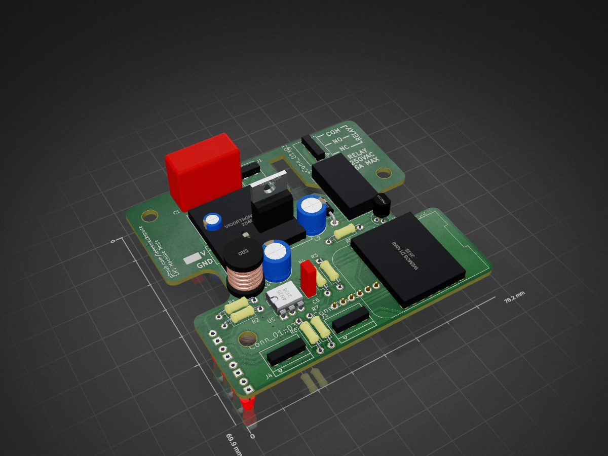
 leedshackspace/machine-access-node2
Hardware interface to the Tool Access API.
Machine node wifi is an open-source printed circuit board by leedshackspace, from the leedshackspace/machine-access-node repository on GitHub. It is a 2-layer board of 76.2 × 69.9 mm with 37 parts on 36 nets, routed with 329 tracks and 17 vias.
It is built around the PN2222A. Its parts include 7 resistors, 6 diodes, 5 capacitors, 5 ICs and 5 connectors. It belongs with the radio and wireless and interfaces and adapters boards of this library.
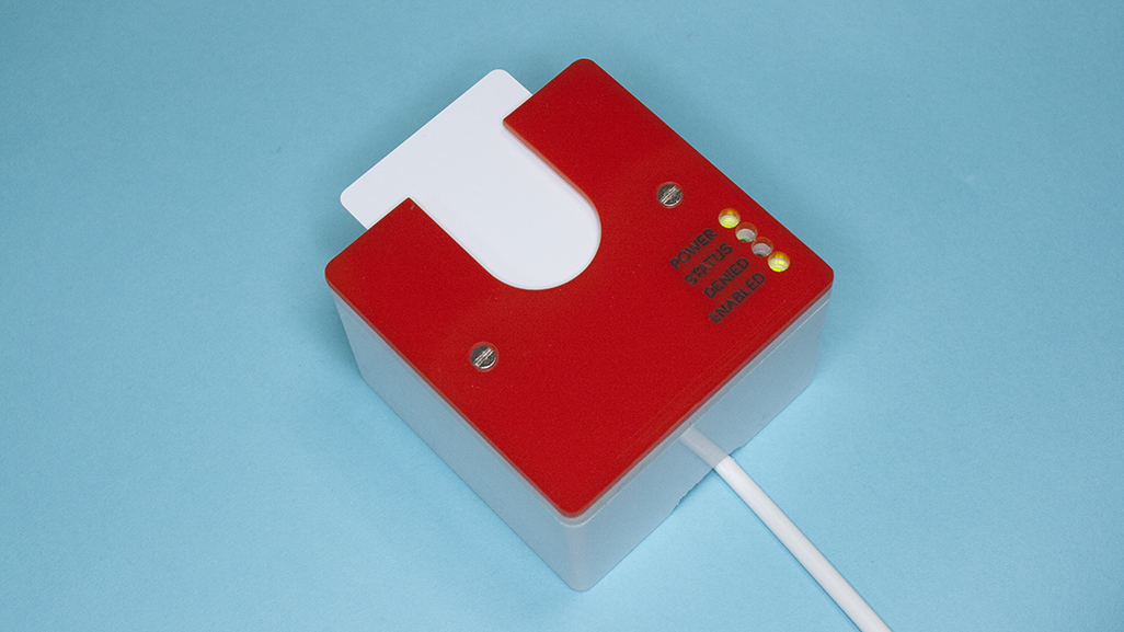
Hardware and firmware to provide restricted access to dangerous and delicate tools. Built around an ESP8266 (WeMos D1 mini) and RFID-RC522 breakout.
Designed to be easy to build for all levels of experience - simply order the PCB from DirtyPCBs or OSHPark and solder the through hole parts to the board. Software builds through the Arduino environment and will flash directly to the WeMos board over USB.
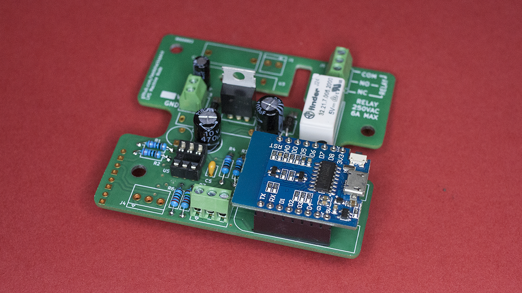
To build a machine node you simply need to acquire a PCB - gerbers are available in the hardware folder - and order the parts listed in the BOM.
There are three power supply options.
C4 if you wish.U2 or D2. Use a jumper wire to bridge D2 and connect the solder jumper JP1.U3 but there should be external fusing as well to protect small gauge cabling coming into the terminals.The relay is rated for 250 V, 6 A max. If you are switching heavy loads it is recommended that you use this to trip an external contactor.
The default state is "Present" mode, that is, the output will turn on when the card is present and it will turn off when it is removed. An as yet untested mode allows the node to read a card once and then keep the output enabled until an external signal is received.
Feel free to test this mode out, you can modify settings in settings.h. Remember to include a button to allow the user to cancel their session.
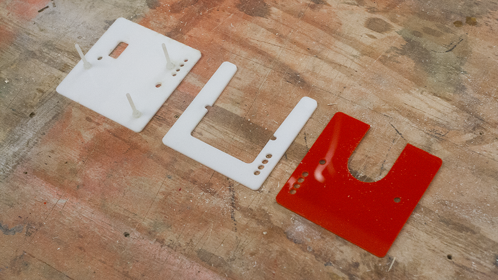
Enclosure parts are for laser cutting and will fit a deep surface mount pattress box available from LAP. You need to countersink the "solid" back plate and fit screws through into the backbox compartment to secure the PCB in place. Nylon screws & nuts are recommended to secure the PCB to minimize any interference with the RFID signal. Typical metal faceplate screws are acceptable to attach the faceplate to the backbox.
Modify settings-example.h and rename as settings.h.
Requires the Tool API server running somewhere accessible, at least until the cards have been cached.
| Qty | Value | Footprint | References |
|---|---|---|---|
| 4 | 1K | Resistors_ThroughHole:R_Axial_DIN0207_L6.3mm_D2.5mm_P10.16mm_Horizontal | R1, R2, R3, R4 |
| 3 | Conn_01x03 | adnbr_pth:CONNECTOR-03-3.5MM | J3, J4, J5 |
| 2 | 1N4001 | Diodes_ThroughHole:D_DO-41_SOD81_P10.16mm_Horizontal | D2, D6 |
| 2 | 2K2 | Resistors_ThroughHole:R_Axial_DIN0207_L6.3mm_D2.5mm_P10.16mm_Horizontal | R5, R6 |
| 2 | Conn_01x02 | adnbr_pth:CONNECTOR-02-3.5MM | J1, J2 |
| 1 | 0.1NF | Capacitors_ThroughHole:C_Rect_L4.0mm_W2.5mm_P2.50mm | C5 |
| 1 | 100U | Capacitors_ThroughHole:CP_Radial_D8.0mm_P3.50mm | C2 |
| 1 | 10K | Resistors_ThroughHole:R_Axial_DIN0207_L6.3mm_D2.5mm_P10.16mm_Horizontal | R7 |
| 1 | 10U | Capacitors_ThroughHole:CP_Radial_D5.0mm_P2.00mm | C3 |
| 1 | 470UF | Capacitors_ThroughHole:CP_Radial_D8.0mm_P3.50mm | C4 |
| 1 | 4N25 | Housings_DIP:DIP-6_W7.62mm | U5 |
| 1 | 5UH | Inductors:INDUCTOR_V | L1 |
| 1 | 5V-JUMP | modules:SOLDER-JUMPER_1-WAY | JP1 |
| 1 | ECQU2A224ML | Capacitors_ThroughHole:C_Rect_L18.0mm_W8.0mm_P15.00mm_FKS3_FKP3 | C1 |
| 1 | FINDER 32.21.7.012.2000 | Relays_ThroughHole:Relay_SPDT_Finder_32.21-x000 | K1 |
| 1 | LM7805_TO220 | TO_SOT_Packages_THT:TO-220-3_Vertical | U2 |
| 1 | NOT-AUTH | LEDs:LED_D3.0mm | D4 |
| 1 | OUTPUT-ACTIVE | LEDs:LED_D3.0mm | D5 |
| 1 | PN2222A | TO_SOT_Packages_THT:TO-92_Molded_Narrow | Q1 |
| 1 | POWER | LEDs:LED_D3.0mm | D1 |
| 1 | RFID-RC522 Reader | Socket_Strips:Socket_Strip_Angled_1x08_Pitch2.54mm | U4 |
| 1 | STATUS | LEDs:LED_D3.0mm | D3 |
| 1 | Vigortronix-VTX-214-005-005 | VTX-214-005-005 | U3 |
| 1 | WeMos D1 Mini | wemos_d1_mini:D1_mini_board | U1 |
The 32 most common of 37 parts.
It measures 76.2 × 69.9 mm and has 2 copper layers, 1.6 mm thick.
37 parts, built around the PN2222A. The full list of its parts is on this page, with links to each part's symbol and footprint where PCBKit's library has them.
From the leedshackspace/machine-access-node repository on GitHub, at the commit this page was made from: the board is hardware/machine-node-wifi.kicad_pcb. PCBKit opens the board in the browser, with nothing to install.
Its repository states no licence, so its author keeps all rights: ask leedshackspace before reusing the design.
skiselev/micro_8088
Micro 8088 - IBM XT Compatible Processor Board based on Faraday FE2010 chipset

Staacks/there.oughta.be
Projects featured on my blog at https://there.oughta.be


plusvic/simplebus2-intercom
General description of the Simplebus2 protocol used by some Comelit's intercoms. Hardware for retransmitting Simplebus2 messages over UART.


