2 layers86.4 × 33 mm
Stm32f1-nrf24l01-transmitter airtronics
laneboysrc/rc-headless-transmitter
DIY 2.4 GHz RC transmitter without display, configurable through smartphone or web browser
36 parts33

 laneboysrc/rc-headless-transmitter33
DIY 2.4 GHz RC transmitter without display, configurable through smartphone or web browser
Stm32f1-nrf24l01-transmitter pcb is an open-source printed circuit board by laneboysrc, from the laneboysrc/rc-headless-transmitter repository on GitHub. It is a 2-layer board of 128 × 47 mm with 79 parts on 56 nets, routed with 401 tracks and 21 vias.
It is built around the STM32F103CBT6, MCP1703A-3302E/MB and PMV30UN2R. Its parts include 29 connectors, 14 capacitors, 13 resistors, 4 ICs and 3 diodes. It belongs with the radio and wireless boards and the STM32 boards of this library.


This project implements a 2.4 GHz RC transmitter using the NRF24L01+ wireless module and the STM32F103C8T6 micro-controller.
The term headless comes from the IT industry, where a headless system is one that does not provide a user interface itself, but is rather configured remotely. Within this project, headless means that the transmitter does not have a display or buttons for configuration. It relies on remote configuration through a web-browser running on a Smartphone, Tablet or computer.
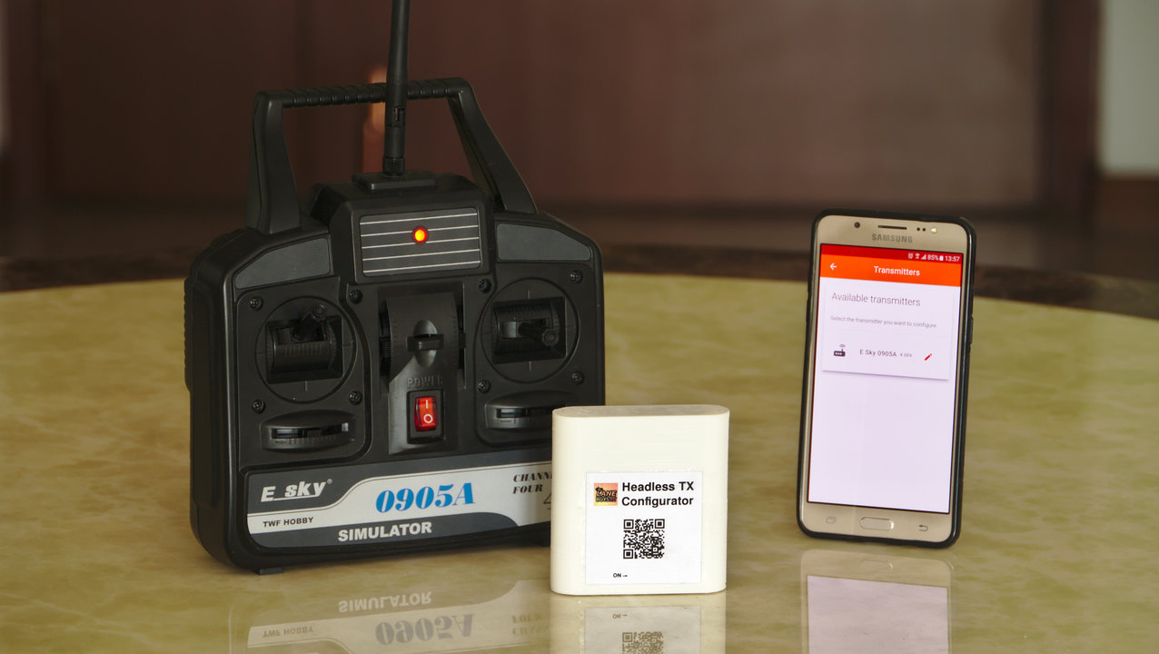
The motivation for this project was to upgrade old AM/FM RC transmitter hardware, and to turn a cheap RC simulator into a fully operational transmitter that supports multiple models.
By keeping the user interface for configuration out of the transmitter, we don't need to perform complicated mechanical modifications to add a display and buttons. We only replace the old electronics with a modern 32 bit ARM micro-controller and a reliable 2.4 GHz transceiver wired on a prototyping board.
The transmitter is currently compatible with HobbyKing HKR3000 and HKR3100 receivers, as well as the LANE Boys RC nrf24le01-rc DIY receivers. It runs off a 1S Li-Ion battery.
The headless transmitter works like any low-end 2.4 GHz RC system on the market: power it on, and use it with the model you have it setup for.
However, unlike low-end transmitters, the headless transmitter supports advanced features like expo, mixing, failsafe and more.
In order to configure those features, you need to use a web-browser on your Smartphone, Tablet or computer.
To be able to connect your Smartphone to the transmitter, we need to translate between different radio protocols: The transmitter uses a proprietary RF protocol, while the Smartphone supports Wi-Fi. This translation takes place in a small, external box called configurator.
When you want to configure your headless transmitter, you turn the configurator on, connect your phone to the Wi-Fi access-point the configurator provides, and launch the configuration web-app to perform the configuration. When you are done, the changes are automatically saved in the transmitter and persist over power cycles.
The configurator is built from an Orange Pi Zero, with an extra RF module for the connection to the headless transmitter.
The Smartphone has a large amount of persistent memory. This allows us to store configurations for multiple models. When we want to reconfigure the transmitter for another model, we simply download the model configuration configuration into the headless transmitter. This only takes a few seconds.
The power consumption of the transmitter is low: A single 800 mAh Li-Ion battery keeps the transmitter running for approximately 15 hours. The configurator is only used rarely and can be powered from a suitable power bank.
When sourcing the modules from China, a transmitter can be built for less than USD 10. The configurator hardware cost is less than USD 20. You only need one configurator, regardless of how many headless transmitters you have.
Please consult the INSTALL.md file for instructions.
The docs/ folder contains various documents explaining details for the architecture.
The headless transmitters hardware is described in the transmitter/ folder.
The configurator is based on the Orange Pi Zero. Its hardware documentation resides in configurator/orangepizero/HARDWARE.md.
The web-app can be accessed from https://laneboysrc.github.io/rc-headless-transmitter
This project is not finished yet. Refer to the TODO list for items that we plan to implement in the future.
At the moment the project has only been tested on Android using Chrome and Firefox, and on PCs running Chrome or Firefox.
| Qty | Value | Footprint | References |
|---|---|---|---|
| 5 | 100n | Capacitor_SMD:C_0603_1608Metric_Pad1.05x0.95mm_HandSolder | C5, C8, C12, C13, C14 |
| 5 | MountingHole | MountingHole:MountingHole_3.2mm_M3_DIN965 | H1, H2, H3, H9, H10 |
| 5 | MountingHole | MountingHole:MountingHole_2.7mm_M2.5_DIN965 | H4, H5, H6, H7, H8 |
| 4 | 1u | Capacitor_SMD:C_0805_2012Metric_Pad1.15x1.40mm_HandSolder | C1, C7, C10, C11 |
| 3 | LED | LED_SMD:LED_0805_2012Metric_Pad1.15x1.40mm_HandSolder | D1, D2, D3 |
| 2 | 100k | Resistor_SMD:R_0805_2012Metric_Pad1.15x1.40mm_HandSolder | R1, R3 |
| 2 | 18 | Resistor_SMD:R_0805_2012Metric_Pad1.15x1.40mm_HandSolder | R5, R6 |
| 2 | 18p | Capacitor_SMD:C_0603_1608Metric_Pad1.05x0.95mm_HandSolder | C2, C3 |
| 2 | 1k5 | Resistor_SMD:R_0805_2012Metric_Pad1.15x1.40mm_HandSolder | R4, R11 |
| 2 | MCP1703A-3302 | Package_TO_SOT_SMD:SOT-23_Handsoldering | U1, U4 |
| 1 | 100nF | Capacitor_SMD:C_0805_2012Metric_Pad1.15x1.40mm_HandSolder | C6 |
| 1 | 10M | Resistor_SMD:R_0805_2012Metric_Pad1.15x1.40mm_HandSolder | R2 |
| 1 | 10k | Resistor_SMD:R_0805_2012Metric_Pad1.15x1.40mm_HandSolder | R10 |
| 1 | 10u | Capacitor_SMD:C_0805_2012Metric_Pad1.15x1.40mm_HandSolder | C4 |
| 1 | 1K5 | Resistor_SMD:R_0805_2012Metric_Pad1.15x1.40mm_HandSolder | R7 |
| 1 | 1k | Resistor_SMD:R_0805_2012Metric_Pad1.15x1.40mm_HandSolder | R13 |
| 1 | 22k | Resistor_SMD:R_0805_2012Metric_Pad1.15x1.40mm_HandSolder | R8 |
| 1 | 33k | Resistor_SMD:R_0805_2012Metric_Pad1.15x1.40mm_HandSolder | R9 |
| 1 | 3k9 | Resistor_SMD:R_0805_2012Metric_Pad1.15x1.40mm_HandSolder | R12 |
| 1 | 47u | Capacitor_SMD:C_0805_2012Metric_Pad1.15x1.40mm_HandSolder | C9 |
| 1 | 8MHz | Crystal:Crystal_SMD_5032-2Pin_5.0x3.2mm | Y1 |
| 1 | BATTERY | Connector_JST:JST_XH_B2B-XH-A_1x02_P2.50mm_Vertical | J19 |
| 1 | BOOT0 | TestPoint:TestPoint_Pad_1.5x1.5mm | TP1 |
| 1 | BOOT1 | TestPoint:TestPoint_Pad_1.5x1.5mm | TP2 |
| 1 | Blue | TestPoint:TestPoint_Pad_1.5x1.5mm | J21 |
| 1 | Buzzer | Connector_JST:JST_XH_B2B-XH-A_1x02_P2.50mm_Vertical | J26 |
| 1 | External charger LED | Connector_JST:JST_XH_B3B-XH-A_1x03_P2.50mm_Vertical | J18 |
| 1 | LED | Connector_JST:JST_XH_B2B-XH-A_1x02_P2.50mm_Vertical | J30 |
| 1 | LIPO_CHARGER_+_PROTECTION | WLA:LiPo_charger_and_protection | U2 |
| 1 | Meter | Connector_JST:JST_XH_B2B-XH-A_1x02_P2.50mm_Vertical | J29 |
| 1 | NRF24 connector | Connector_JST:JST_XH_B8B-XH-A_1x08_P2.50mm_Vertical | J27 |
| 1 | PA1/A1 | Connector_JST:JST_XH_B3B-XH-A_1x03_P2.50mm_Vertical | J1 |
| 1 | PA2/A2 | Connector_JST:JST_XH_B3B-XH-A_1x03_P2.50mm_Vertical | J2 |
| 1 | PA3/A3 | Connector_JST:JST_XH_B3B-XH-A_1x03_P2.50mm_Vertical | J3 |
| 1 | PA4/A4 | Connector_JST:JST_XH_B3B-XH-A_1x03_P2.50mm_Vertical | J4 |
| 1 | PA5/A5 | Connector_JST:JST_XH_B3B-XH-A_1x03_P2.50mm_Vertical | J5 |
| 1 | PA6/A6 | Connector_JST:JST_XH_B3B-XH-A_1x03_P2.50mm_Vertical | J6 |
| 1 | PA7/A7 | Connector_JST:JST_XH_B3B-XH-A_1x03_P2.50mm_Vertical | J7 |
| 1 | PB0/A8 | Connector_JST:JST_XH_B3B-XH-A_1x03_P2.50mm_Vertical | J8 |
| 1 | PB1/A9 | Connector_JST:JST_XH_B3B-XH-A_1x03_P2.50mm_Vertical | J9 |
| 1 | PB10 | Connector_JST:JST_XH_B3B-XH-A_1x03_P2.50mm_Vertical | J16 |
| 1 | PB11 | Connector_JST:JST_XH_B3B-XH-A_1x03_P2.50mm_Vertical | J17 |
| 1 | PB3 | Connector_JST:JST_XH_B3B-XH-A_1x03_P2.50mm_Vertical | J10 |
| 1 | PB4 | Connector_JST:JST_XH_B3B-XH-A_1x03_P2.50mm_Vertical | J11 |
| 1 | PB5 | Connector_JST:JST_XH_B3B-XH-A_1x03_P2.50mm_Vertical | J12 |
| 1 | PB6 | Connector_JST:JST_XH_B3B-XH-A_1x03_P2.50mm_Vertical | J13 |
| 1 | PB7 | Connector_JST:JST_XH_B3B-XH-A_1x03_P2.50mm_Vertical | J14 |
| 1 | PB8 | Connector_JST:JST_XH_B3B-XH-A_1x03_P2.50mm_Vertical | J15 |
| 1 | PMV30UN | Package_TO_SOT_SMD:SOT-23_Handsoldering | Q1 |
| 1 | POWER SWITCH | Connector_JST:JST_XH_B2B-XH-A_1x02_P2.50mm_Vertical | J22 |
| 1 | RESET | tact-switch:Tact switch 6x4x3 | SW1 |
| 1 | Red | TestPoint:TestPoint_Pad_1.5x1.5mm | J20 |
| 1 | SPEAKER | Buzzer_Beeper:MagneticBuzzer_PUI_AT-0927-TT-6-R | SP1 |
| 1 | STM32F103CBT6 | Package_QFP:LQFP-48_7x7mm_P0.5mm | U3 |
| 1 | SWD | Connector_PinHeader_2.54mm:PinHeader_1x03_P2.54mm_Vertical | J25 |
| 1 | UART | Connector_PinHeader_2.54mm:PinHeader_1x03_P2.54mm_Vertical | J24 |
| 1 | USB | Connector_JST:JST_XH_B4B-XH-A_1x04_P2.50mm_Vertical | J23 |
laneboysrc/rc-headless-transmitter
DIY 2.4 GHz RC transmitter without display, configurable through smartphone or web browser

laneboysrc/rc-headless-transmitter
DIY 2.4 GHz RC transmitter without display, configurable through smartphone or web browser

laneboysrc/rc-headless-transmitter
DIY 2.4 GHz RC transmitter without display, configurable through smartphone or web browser

laneboysrc/rc-headless-transmitter
DIY 2.4 GHz RC transmitter without display, configurable through smartphone or web browser


Daniel-Alencar/MiniEasy
Esquemático KiCad 10 de um altímetro barométrico de recuperação dupla (apogeu + principal), equivalente em função ao Altus Metrum EasyMini: sensor barométrico, registro de voo em flash, dois canais pirotécnicos com…


windbird-sensor/windbird-fox-electronics
This repository contains the electronic parts of the Windbird wind sensor.


It measures 128 × 47 mm and has 2 copper layers, 1.6 mm thick.
79 parts, built around the STM32F103CBT6, MCP1703A-3302E/MB and PMV30UN2R. The full list of its parts is on this page, with links to each part's symbol and footprint where PCBKit's library has them.
From the laneboysrc/rc-headless-transmitter repository on GitHub, at the commit this page was made from: the board is transmitter/electronics/pcb/stm32f1-nrf24l01-transmitter-pcb.kicad_pcb. PCBKit opens the board in the browser, with nothing to install.
Its repository states no licence, so its author keeps all rights: ask laneboysrc before reusing the design.