2 layers140 × 85 mm

 lampmerchant/tashrecorder8
Clone of the Farallon MacRecorder and Apple MIDI Interface.
Tashrecorder is an open-source printed circuit board by lampmerchant, from the lampmerchant/tashrecorder repository on GitHub, published under the GPL-3.0 licence. It is a 4-layer board of 56.6 × 57.7 mm with 53 parts on 29 nets, routed with 278 tracks and 0 vias.
It is built around the OPA2337UA, LM385Z-2.5 and RCJ-013. Its parts include 14 resistors, 13 capacitors, 7 diodes, 4 ICs and 3 connectors. It belongs with the audio and music and retro computing and games boards and the PIC boards of this library.


This is a simple (but dense) design, using all through hole components. It's designed this way to be period correct and easy to build for people who don't like soldering SMT components.
This folder contains the source KiKad files for the main board. Please check the Panels subfolder for the FR-4 front and back plates.
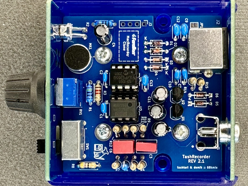
Here is the BOM for the main board. Part number are what was tested on prototypes board but you may find alternatives easily, especially resistors and sockets
| Reference(s) | Value | Quantity | Notes | Part number |
|---|---|---|---|---|
| C1, 2, 7, 9-10, 12-13 | 100nF | 7 | ceramic capacitor 5.08mm | Weltron 453358 |
| C3 | 6800pF | 1 | film capacitor 5mm | Wima FKS2G016801B00KSSD |
| C6 | 680pF | 1 | film capacitor 5mm | Wima FKP2J006801D00HSSD |
| C4, C5, C8, C11 | 22uF | 4 | aluminium electrolytic capacitor | Panasonic ECA-1HHG220I |
| D1 to D6 | 1N4148 | 6 | general purpose switching diode | Vishay 1N4148-TAP |
| D7 | Red | 1 | High efficiency 20000-30000mcd 5mm LED | TRU TC-10551696 |
| J1 | RCA | 1 | RCA Phono Connector | CUI Devices RCJ-013 |
| J2 | Connector | 1 | Circular Mini-DIN Connectors 8P | Kycon KMDGX-8S-AS |
| MK1 | Micro | 1 | omnidirectional electret microphone | DB Unlimited MO093803-1 |
| R1, R2, R6 | 2.4kΩ | 3 | standard 0.25W metal film resistor | TRU MF0W4FF2401 |
| R3, R12 | 1.2kΩ | 2 | standard 0.25W carbon film resistor | TRU CFR0W4J0122 |
| R4, R5, R7, R9 | 220kΩ | 4 | standard 0.25W carbon film resistor | TRU CFR0W4J0224 |
| R8, R14, R15 | 47Ω | 3 | standard 0.25W carbon film resistor | TRU CFR0W4J0470 |
| R10 | 4.7kΩ | 1 | standard 0.25W carbon film resistor | TRU CFR0W4J0472 |
| R11 | 10kΩ | 1 | standard 0.25W carbon film resistor | TRU CFR0W4J0103 |
| RV1 | 100kΩ | 1 | audio 100kΩ panel potentiometer | Bourns PTD901-2015K-A104 |
| SW1 | SPDT | 1 | slide switches right angle | E-Switch EG1224 |
| U1, U2 | 2.5V | 2 | 2.5V TO-92-3 20mA voltage reference | ON Semi LM385Z-2.5 |
| U3 | OPA2337 | 1 | low power RR out CMOS op-amp | Texas OPA2337PA |
| U4 | PIC | 1 | 8-bit Microcontrollers DIP PIC12F1501 | MC PIC12F1501-I/P |
| Case | ABS | 1 | Instrument Case, ABS 2.6x2.6" | HM 1593K(TBU|GY|BK) |
| PCB Screws | #4 | 4 | Phillips Pan Head screws #4 x 1/4" | SERPAC 6004 |
| Socket | DIP-8 | 2 | DIP-8 socket | TRU TC-A 08-LC-TT-203 |
| Knob | Blue | 1 | knob for Ø 6 mm 18 teeth shafts | PSP 49009-BL |
Using sockets is recommended because it will allow you to reclaim the microcontroler and op-amp. This will also allow you to upgrade the firmware if a future firmware is released.
Here is a complete mouser. It includes lots of 10 when that was cheaper. You may have extra components
Main PCB is 4 layers. Panels are simple 2 layers boards. The gerbers are avaible in the release section. Check for the following files:
You should be use any mainstream PCB manufacturer for theses. Nothing special about them. PCB thickness should be 1.6mm
On JLCPCB, select "Specify a location" to the option "Remove Order Number" for all of them
Building is straightworfard. It's recommended to start with small components first (diodes, then resistor, LED), then other components, and connectors last. For Japanase mounted resistors, the resistor will go on the circle side
| Qty | Value | Footprint | References |
|---|---|---|---|
| 7 | 100nF | Capacitor_THT:C_Disc_D4.3mm_W1.9mm_P5.00mm | C1, C2, C7, C9, C10, C12, C13 |
| 6 | 1N4148 | Diode_THT:D_DO-35_SOD27_P7.62mm_Horizontal | D1, D2, D3, D4, D5, D6 |
| 4 | 220kΩ | Resistor_THT:R_Axial_DIN0207_L6.3mm_D2.5mm_P2.54mm_Vertical | R4, R5, R7, R9 |
| 4 | 22uF | Capacitor_THT:CP_Radial_D5.0mm_P2.50mm | C4, C5, C8, C11 |
| 4 | M3 | MountingHole:MountingHole_3.2mm_M3_Pad | H1, H2, H3, H4 |
| 2 | 2.4kΩ | Resistor_THT:R_Axial_DIN0207_L6.3mm_D2.5mm_P7.62mm_Horizontal | R1, R2 |
| 2 | 47Ω | Resistor_THT:R_Axial_DIN0207_L6.3mm_D2.5mm_P2.54mm_Vertical | R14, R15 |
| 2 | LM385Z-2.5 | Package_TO_SOT_THT:TO-92_HandSolder | U1, U2 |
| 2 | LOGO | LOGO | G***, G*** |
| 2 | LOGO | MacRecorder:Farallon | GB, GF |
| 1 | 1.2kΩ | Resistor_THT:R_Axial_DIN0207_L6.3mm_D2.5mm_P2.54mm_Vertical | R12 |
| 1 | 1.2kΩ | Resistor_THT:R_Axial_DIN0207_L6.3mm_D2.5mm_P7.62mm_Horizontal | R3 |
| 1 | 100k | MacRecorder:PTD9011015FA203 | RV1 |
| 1 | 10kΩ | Resistor_THT:R_Axial_DIN0207_L6.3mm_D2.5mm_P2.54mm_Vertical | R11 |
| 1 | 2.4kΩ | Resistor_THT:R_Axial_DIN0207_L6.3mm_D2.5mm_P2.54mm_Vertical | R6 |
| 1 | 4.7kΩ | Resistor_THT:R_Axial_DIN0207_L6.3mm_D2.5mm_P2.54mm_Vertical | R10 |
| 1 | 47Ω | Resistor_THT:R_Axial_DIN0207_L6.3mm_D2.5mm_P7.62mm_Horizontal | R8 |
| 1 | 6800pF | Capacitor_THT:C_Rect_L7.2mm_W4.5mm_P5.00mm_FKS2_FKP2_MKS2_MKP2 | C3 |
| 1 | 680pF | Capacitor_THT:C_Rect_L7.2mm_W4.5mm_P5.00mm_FKS2_FKP2_MKS2_MKP2 | C6 |
| 1 | Conn_01x04 | Connector_PinHeader_2.54mm:PinHeader_1x04_P2.54mm_Vertical | J3 |
| 1 | EG 1224 SPDT | MacRecorder:EG1224 | SW1 |
| 1 | GPIn to GND | Jumper:SolderJumper-2_P1.3mm_Open_Pad1.0x1.5mm | JP1 |
| 1 | LED | LED_THT:LED_D5.0mm_Horizontal_O6.35mm_Z9.0mm | D7 |
| 1 | Microphone | CMA-4544PF-W:CMA4544PFW | MK1 |
| 1 | Mini-DIN-8 | Mini-DIN-8:57492681 | J2 |
| 1 | OPA2337 | Package_DIP:DIP-8_W7.62mm_LongPads | U3 |
| 1 | PIC12F1501-xP | Package_DIP:DIP-8_W7.62mm_LongPads | U4 |
| 1 | RCJ-013 | MacRecorder:CUI_RCJ-013 | J1 |


abzman/Exidy-Sorcerer-Stuff
boards and maybe software for the exidy sorcerer

punkfab/pcb-corpus
235 real KiCad boards from open-source hardware repositories, prepared as a placement and routing benchmark

murexrobotics/electrical
Highly integrated electronics design and printed circuit boards (PCBs) for the MATE ROV Competition. Attempt the impossible.
It measures 56.6 × 57.7 mm and has 4 copper layers, 1.6 mm thick.
53 parts, built around the OPA2337UA, LM385Z-2.5 and RCJ-013. The full list of its parts is on this page, with links to each part's symbol and footprint where PCBKit's library has them.
From the lampmerchant/tashrecorder repository on GitHub, at the commit this page was made from: the board is pcb/TashRecorder.kicad_pcb and its schematic pcb/Panels/Back/tashrecorder_BP.kicad_sch. PCBKit opens the board in the browser, with nothing to install.
Its repository publishes it under the GPL-3.0 licence: you may reuse it on that licence's terms (keep the author's notice, and for a copyleft licence share your changes alike).