
2 layers9.9 × 7.4 mm
 lambdaBoost/polaroid-experiments13
Accompanying files for the youtube video
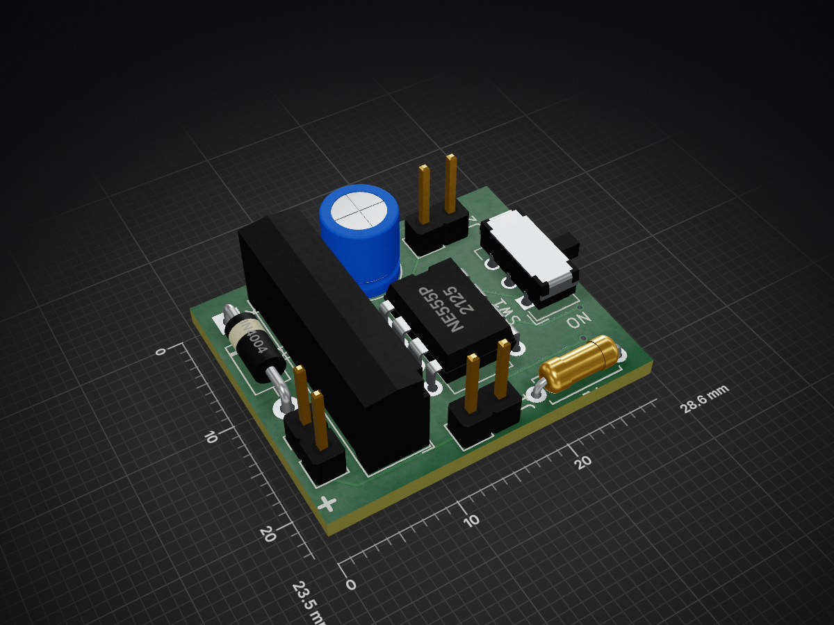
Sx-70 timer is an open-source printed circuit board by lambdaBoost, from the lambdaBoost/polaroid-experiments repository on GitHub. It is a 2-layer board of 28.6 × 23.5 mm with 9 parts on 10 nets, routed with 62 tracks and 6 vias.
It is built around the NE555P. Its parts include 3 connectors, 2 switches, 1 capacitor, 1 resistor and 1 IC.
This repo contains both files referred to in the youtube video here and contains notes on my ongoing attempts to improve DIY peel apart film recipes.
The recipe is given in the video and may also be found at Alec Myers website.
My notes to date are:
My attempts at coloring these images with additive screens will also be documented here in due course.
All the pcb schematics and raw gerber files you need to build this are in the respective folder. You'll need to make 2 pins to solder onto the board which will be inserted into the camera. I machined mine from brass, but 1.5mm wire will probably be fine.
This one is a bit trickier to manufacture since it requires a small lathe and milling machine. I am fortunate enough to have an Emco Unimat. I would recommend against 3d printing this - it needs to be very strong, so I used mild steel.
This is a tiny pcb with just a switch and 2 smd capacitors. It is quite self expnalatory in the video, but it does require some skill and care to fit to the camera - take your time.
I test everything with a flat lithium battery inserted into a film cartridge. It supplies a stable 6v voltage through a little step up converter board. It can''t supply the same current as the original Polaroid batteries but it's enough to cycle everything.
| Qty | Value | Footprint | References |
|---|---|---|---|
| 3 | Conn_01x02_Male | Connector_PinHeader_2.54mm:PinHeader_1x02_P2.54mm_Vertical | J1, J2, J3 |
| 1 | 1N4004 | Diode_THT:D_DO-41_SOD81_P10.16mm_Horizontal | D1 |
| 1 | C | Capacitor_THT:C_Radial_D6.3mm_H7.0mm_P2.50mm | C1 |
| 1 | NE555P | Package_DIP:DIP-8_W7.62mm | U1 |
| 1 | R | Resistor_THT:R_Axial_DIN0207_L6.3mm_D2.5mm_P7.62mm_Horizontal | R1 |
| 1 | SILxx-1Axx-71x | Relay_THT:Relay_SPST_StandexMeder_SIL_Form1A | K1 |
| 1 | SW_DPDT_x2 | Button_Switch_THT:SW_CuK_JS202011AQN_DPDT_Angled | SW1 |

baldengineer/bit-preserve
Project for capturing vintage, classic, aka old computer schematics in KiCad.

The-Invent0r/8-bit-Computer-PCB
These are the KiCAD files for my 8-Bit Computer.

DarcyJProjects/touchtone555
An open-source DIY, NE555-based analogue synthesizer - play notes with a stylus


benjiaomodular/SynthCard
I designed this project with the help of PCBWay. You can get a copy of these cards through the PCBWay Shared Projects page.

fortinsylvain/MyCpu
Home brew CPU Hardware with 1-bit ALU implementation using 74LSxx, a micro-code and assembler coded in C#.

hackup/C128Diag
Replica of the Commodore C128 Diagnostic Test cartridge Assy No. 325093-01.
It measures 28.6 × 23.5 mm and has 2 copper layers, 1.6 mm thick.
9 parts, built around the NE555P. The full list of its parts is on this page, with links to each part's symbol and footprint where PCBKit's library has them.
From the lambdaBoost/polaroid-experiments repository on GitHub, at the commit this page was made from: the board is sx-70-timer/sx-70_timer.kicad_pcb and its schematic sx-70-iso-selector/capacitor_switch.kicad_sch. PCBKit opens the board in the browser, with nothing to install.
Its repository states no licence, so its author keeps all rights: ask lambdaBoost before reusing the design.