
2 layers103.8 × 50 mm
Galagino pcb set
harbaum/galagino
A Galaga, Pac-Man and Donkey Kong arcade emulator for the ESP32
26 parts558

 lalithk06/PID-Line-Follower
An ESP32-powered autonomous line follower built on a purpose-designed PCB featuring structured power zoning, transient protection, analog sensor acquisition, and efficient motor driving via the TB6612FNG
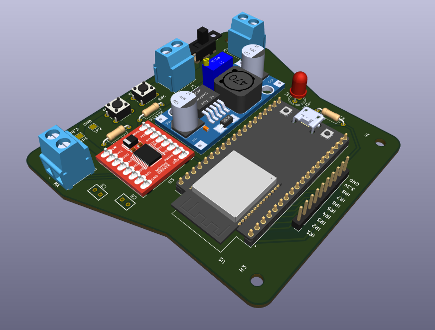
Line Follower is an open-source printed circuit board by lalithk06, from the lalithk06/PID-Line-Follower repository on GitHub. It is a 2-layer board of 95.5 × 84.7 mm with 23 parts on 44 nets, routed with 120 tracks and 3 vias.
It is built around the ESP32-DEVKITC-VE. Its parts include 4 connectors, 3 resistors, 3 ICs, 3 switches and 2 capacitors. It belongs with the robots and motor control boards and the ESP32 boards of this library.
A compact and efficient line follower robot built using the ESP32
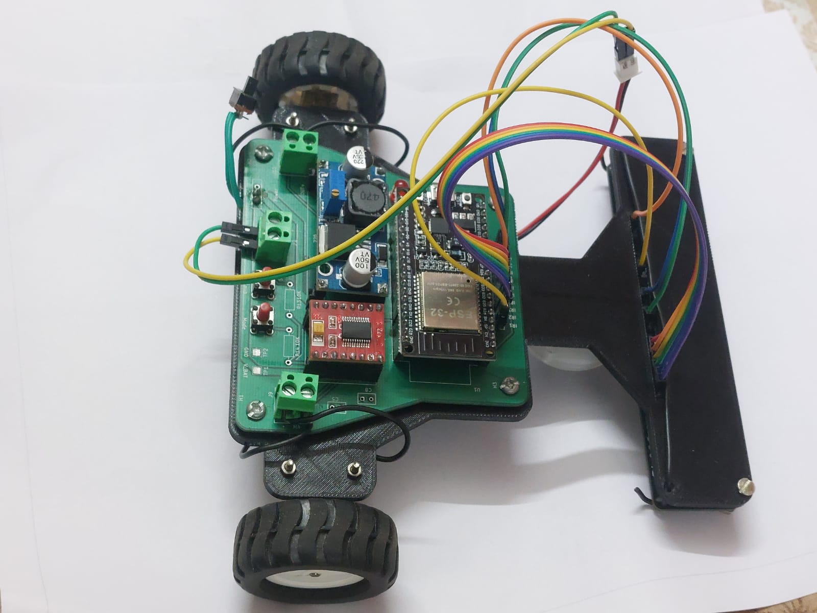
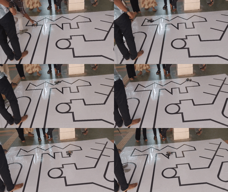
This project showcases the schematic and PCB design of a reliable line follower robot capable of high-speed tracking with stable power delivery and clean motor control. It is designed as a practical exploration of real-world embedded hardware development and PCB design workflows.
PID-Line-Follower
│
├── Firmware
│   └── Arduino_Code
│
├── Hardware
│   ├── Images
│   ├── Schematic
│   ├── Datasheet
│   └── Pin_Mapping
│
├── README.md
└── .gitignoreTo design and develop a robust hardware platform for a line follower robot that demonstrates:
| No. | Component | Role |
|---|---|---|
| 1 | ESP32 DevKit (38-pin) | Main microcontroller with Wi-Fi & BLE |
| 2 | TB6612FNG | Dual motor driver |
| 3 | LM2596 Buck Converter | Efficient voltage regulation |
| 4 | IR Sensor Array (8-channel) | Line detection |
| 5 | Push Buttons (2x) | Calibration & mode selection |
| 6 | Battery Input + Slide Switch | Power control |
| 7 | Capacitors | Filtering & decoupling |
| 8 | Mounting Holes | Mechanical stability |
Battery → Slide Switch → LM2596 Buck → 3.3V Rail
Design considerations:
✅ Wide power traces for motor current
✅ Dedicated ground plane
✅ Local decoupling near driver and ESP32
✅ Separate motor and logic routing where possible
The robot firmware is written for the ESP32 using the Arduino framework.
Key features of the control software:
• Multi-sensor line detection
• Adaptive speed control
• PID-based steering correction
• Calibration routines for sensor tuning
Firmware source code is available in the Firmware directory.
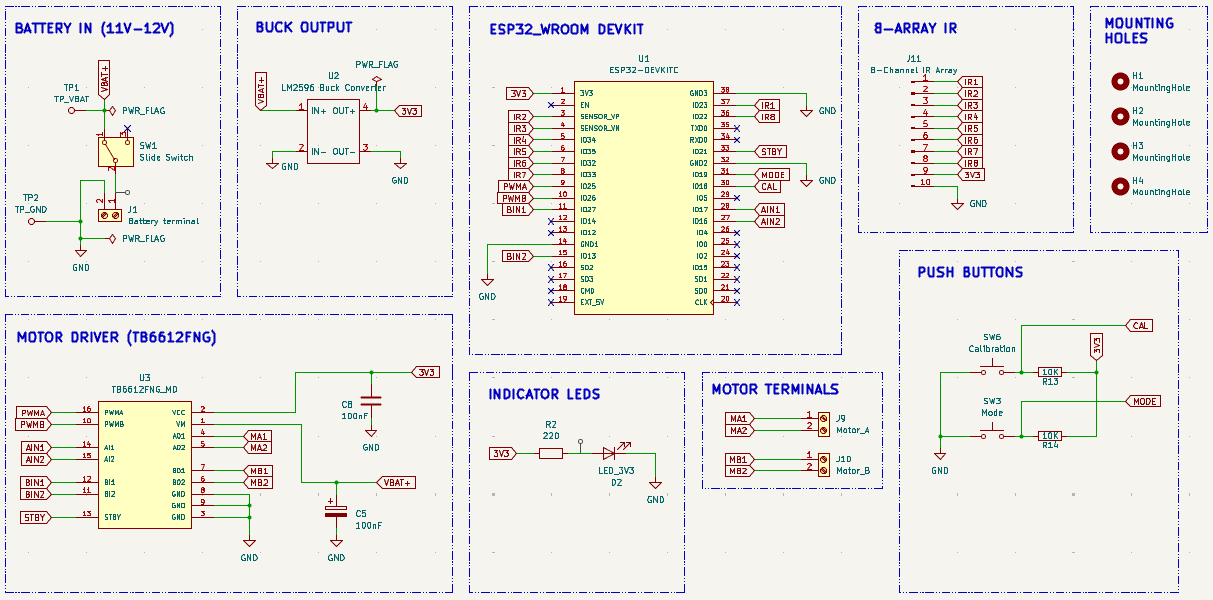
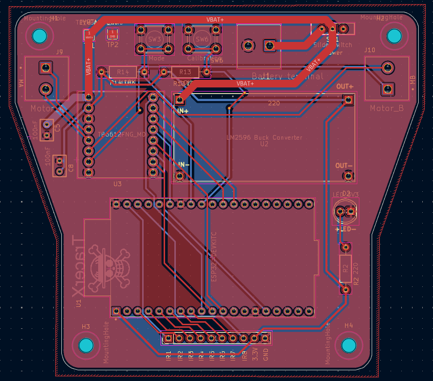
✅ Stable buck-regulated power supply
✅ High-efficiency TB6612FNG motor control
✅ Mixed analog + digital sensor interface
✅ Compact 2-layer PCB
✅ Ground plane for noise reduction
✅ Designed following practical PCB routing guidelines
This project helped strengthen understanding of:
| Qty | Value | Footprint | References |
|---|---|---|---|
| 4 | MountingHole | MountingHole:MountingHole_3.2mm_M3 | H1, H2, H3, H4 |
| 2 | 100nF | Capacitors:C320C | C5, C8 |
| 2 | 10K | Resistor_THT:R_Axial_DIN0207_L6.3mm_D2.5mm_P10.16mm_Horizontal | R13, R14 |
| 1 | 220 | Resistor_THT:R_Axial_DIN0207_L6.3mm_D2.5mm_P10.16mm_Horizontal | R2 |
| 1 | 8-Channel IR Array | Connector_PinHeader_2.54mm:PinHeader_1x10_P2.54mm_Vertical | J11 |
| 1 | Battery terminal | Screw Terminal:CUI_TB007-508-02BE | J1 |
| 1 | Calibration | Button_Switch_THT:SW_PUSH_6mm | SW6 |
| 1 | ESP32-DEVKITC | ESP-WROOM:MODULE_ESP32-DEVKITC | U1 |
| 1 | LED_3V3 | LED_THT:LED_D5.0mm | D2 |
| 1 | LM2596 Buck Converter | Buck_Converter:LM2596_Buck_Module | U2 |
| 1 | LOGO | OP:OP | G*** |
| 1 | Mode | Button_Switch_THT:SW_PUSH_6mm | SW3 |
| 1 | Motor_A | Screw Terminal:CUI_TB007-508-02BE | J9 |
| 1 | Motor_B | Screw Terminal:CUI_TB007-508-02BE | J10 |
| 1 | Slide Switch | Button_Switch_THT:SW_Slide-03_Wuerth-WS-SLTV_10x2.5x6.4_P2.54mm | SW1 |
| 1 | TB6612FNG_MD | TB6612FNG:TB6612FNG_Driver | U3 |
| 1 | TP_GND | TestPoint:TestPoint_Pad_2.0x2.0mm | TP2 |
| 1 | TP_VBAT | TestPoint:TestPoint_Pad_2.0x2.0mm | TP1 |
harbaum/galagino
A Galaga, Pac-Man and Donkey Kong arcade emulator for the ESP32

RParkerE/OpenSilicon
OpenSilicon enables DIY semiconductor fabrication with open-source guides for building IC equipment at home. The project includes BOMs, 3D files, firmware, and PDKs, supporting makers and researchers in chip fabrication.

cole8888/SRNE-Solar-Charge-Controller-Monitor
Read data from SRNE solar charge controllers.


ste2425/PSP-Bluetooth-AVConnector
An AV-Out Breakout library for the PSP. Providing Kicad symbols and footprints to interface with the PSP 2/3K AVOut socket (also known as the TVOut socket)

It measures 95.5 × 84.7 mm and has 2 copper layers, 1.6 mm thick.
23 parts, built around the ESP32-DEVKITC-VE. The full list of its parts is on this page, with links to each part's symbol and footprint where PCBKit's library has them.
From the lalithk06/PID-Line-Follower repository on GitHub, at the commit this page was made from: the board is Hardware/Line_Follower/Line_Follower.kicad_pcb and its schematic Hardware/Line_Follower/Line_Follower.kicad_sch. PCBKit opens the board in the browser, with nothing to install.
Its repository states no licence, so its author keeps all rights: ask lalithk06 before reusing the design.