
2 layers224.2 × 153.7 mm
 krystofh/kitchen_timer
TimeUp kitchen timer based on 4-digit segment display, Raspberry Pi Pico and running on Zephyr RTOS
Kitchen timer is an open-source printed circuit board by krystofh, from the krystofh/kitchen_timer repository on GitHub, published under the Apache-2.0 licence. It is a 2-layer board of 74.2 × 79 mm with 39 parts on 66 nets, routed with 336 tracks and 1 via.
It is built around the BC327 and BC337. Its parts include 14 resistors, 5 transistors, 5 switches, 3 connectors and 2 ICs. It belongs with the lEDs and displays boards and the RP2040 boards of this library.
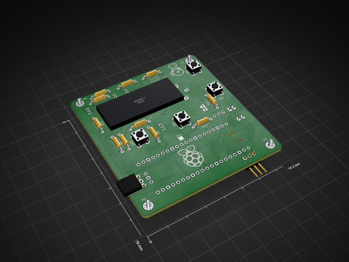
Kitchen timer based on 4-digit 8-segment display 3461BS and RP Pico
 |
|---|
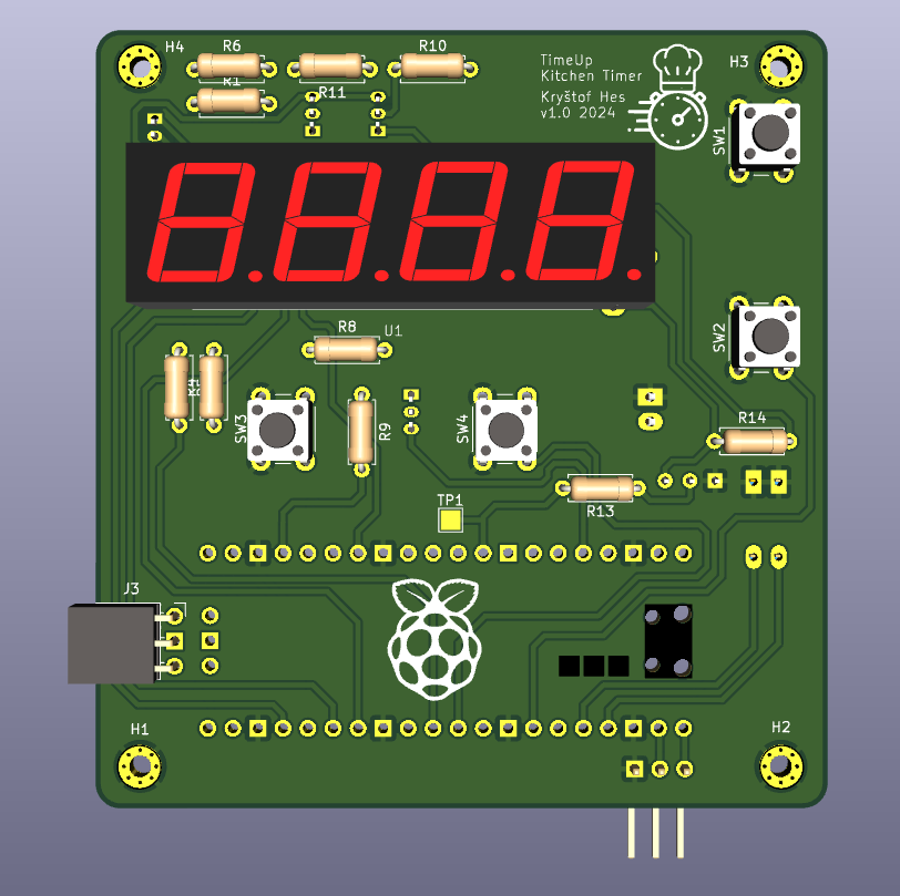
| Front view of the PCB |
 |
|---|
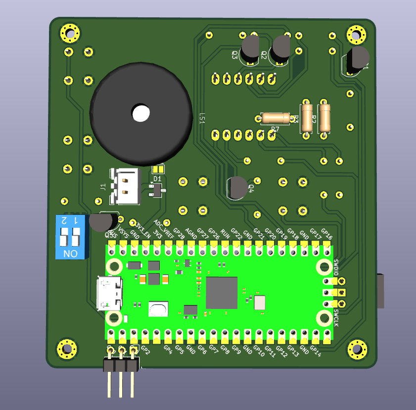
| Back view of the PCB |
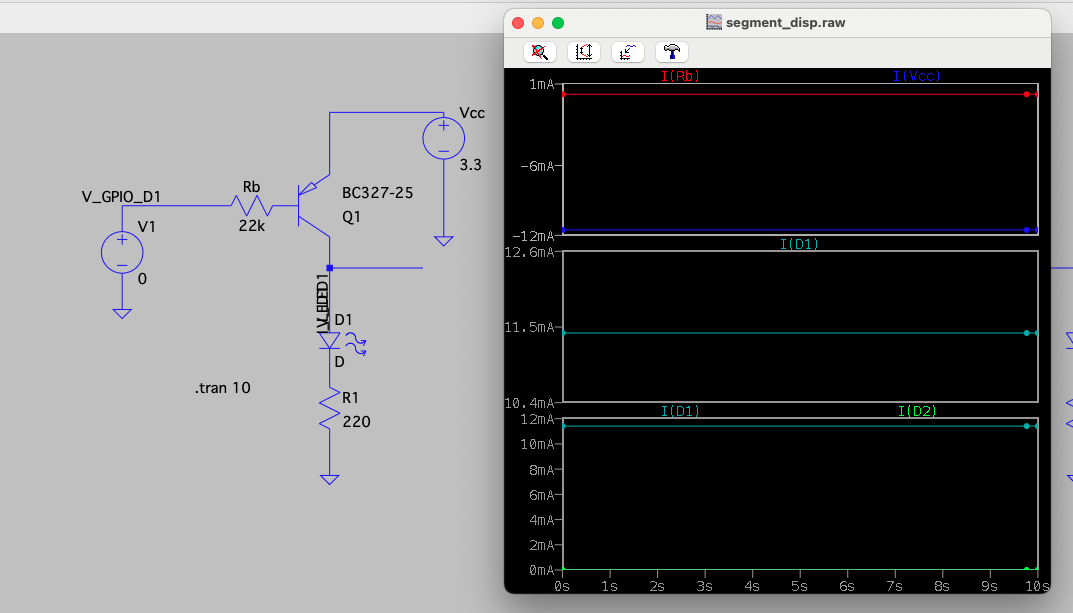
The used display is a common anode display. The datasheet specifies 10 mA typical current for the optical characteristics of a segment. The GPIOs of RP Pico can provide 12 mA max. The built-in 3V3OUT voltage regulator can output up to 300 mA, which is sufficient for all 8 segemts. Not the full 32 segments are needed since the digits are displayed with a given refresh rate sequentially once at a time. Simulation using LTSpice and PNP transistor BCS327-25 leads to the choice of resistor value
s with 220 Ohm and 22k. For the edge cases "1 segment" and "8 segments" the current limitations are fulfilled.

Start by enabling PWM in the prj.conf file: CONFIG_PWM=y
In the .overlay file, enable the node pwm_led0 by setting the status:
&pwm_led0 {
status = "okay";
};
Check the PWM generator corresponding to the GPIO. For RP Pico, these are:

It results in a table:
| PWM channel Nr. | PWM channel | GPIO |
|---|---|---|
| 0 | 0A | 0 |
| 1 | 0B | 1 |
| 2 | 1A | 2 |
| .. | .. | .. |
| 15 | 7B | 15 |
| 0 ❗ | 0A | 16 |
| 1 | 0B | 17 |
This means that to set PWM ON GPIO 27, we will need PWM 5B with the number 11.
In the .dts file (not the overlay!), edit the pwm_leds node:
 pwm_leds {
 	compatible = "pwm-leds";
 	status = "disabled";
 	pwm_led0: pwm_led_0 {
 		pwms = <&pwm 11 PWM_MSEC(20) PWM_POLARITY_NORMAL>;
 		label = "PWM_LED";
 	};
 };
Next, set the PWM on the specific pin. In the rpi_pico-common.dtsi:
 &pwm {
 pinctrl-0 = <&pwm_ch5b_default>;
 pinctrl-names = "default";
 };
Finally, add the pinmux in rpi_pico-pinctrl.dtsi for GPIO 27:
pwm_ch5b_default: pwm_ch5b_default {
 	group1 {
 		pinmux = <PWM_5B_P27>;
 	};
 };
Follow the examples such as PWM Blinky and compile them with the changed devicetree. If it works, start coding your own application.
Device tree nodes are aliased like in the picture below. The change from - to _ is mandatory!

In the .c code, the alias is used like:
static const struct pwm_dt_spec my_variable = PWM_DT_SPEC_GET(DT_ALIAS(buzzer_dev));| Qty | Value | Footprint | References |
|---|---|---|---|
| 8 | 220 | Resistor_THT:R_Axial_DIN0207_L6.3mm_D2.5mm_P10.16mm_Horizontal | R1, R2, R3, R4, R5, R6, R7, R8 |
| 4 | 22k | Resistor_THT:R_Axial_DIN0207_L6.3mm_D2.5mm_P10.16mm_Horizontal | R9, R10, R11, R12 |
| 4 | BC327 | Package_TO_SOT_THT:TO-92_Inline | Q1, Q2, Q3, Q4 |
| 4 | M2 hole | MountingHole:MountingHole_2.2mm_M2_Pad_Via | H1, H2, H3, H4 |
| 2 | 1k | Resistor_THT:R_Axial_DIN0207_L6.3mm_D2.5mm_P10.16mm_Horizontal | R13, R14 |
| 2 | LOGO | LOGO | G***, G*** |
| 1 | 4041BS-1 | Custom_footprints:Segment_display_4041BS-1 | U1 |
| 1 | BC337 | Package_TO_SOT_THT:TO-92L_Inline_Wide | Q5 |
| 1 | BTN_A | Button_Switch_THT:SW_PUSH_6mm_H4.3mm | SW1 |
| 1 | BTN_B | Button_Switch_THT:SW_PUSH_6mm_H4.3mm | SW2 |
| 1 | BTN_C | Button_Switch_THT:SW_PUSH_6mm_H4.3mm | SW3 |
| 1 | BTN_D | Button_Switch_THT:SW_PUSH_6mm_H4.3mm | SW4 |
| 1 | JST_2pin_2.5mm | Custom_footprints:JST_2pin_2.54mm_female | J1 |
| 1 | PWM_SPEAKER | TestPoint:TestPoint_Pad_2.0x2.0mm | TP1 |
| 1 | Pico | Custom_footprints:RPi_Pico_SMD_TH | U2 |
| 1 | SCHOTTKY_JUMPER | Jumper:SolderJumper-2_P1.3mm_Open_TrianglePad1.0x1.5mm | JP1 |
| 1 | SEMTECH BAT54S | Custom_footprints:SOT-23_Handsoldering_renumbered | D1 |
| 1 | SWD | Connector_PinSocket_2.54mm:PinSocket_1x03_P2.54mm_Horizontal | J3 |
| 1 | SW_DIP_x02 | Package_DIP:DIP-4_W7.62mm_LongPads | SW5 |
| 1 | Speaker_Crystal | Custom_footprints:Piezzo_10mm_6.5mm_combined | LS1 |
| 1 | UART | Connector_PinHeader_2.54mm:PinHeader_1x03_P2.54mm_Horizontal | J2 |
It measures 74.2 × 79 mm and has 2 copper layers, 1.6 mm thick.
39 parts, built around the BC327 and BC337. The full list of its parts is on this page, with links to each part's symbol and footprint where PCBKit's library has them.
From the krystofh/kitchen_timer repository on GitHub, at the commit this page was made from: the board is electronics/kitchen_timer/kitchen_timer.kicad_pcb and its schematic electronics/kitchen_timer/charging_and_audio.kicad_sch. PCBKit opens the board in the browser, with nothing to install.
Its repository publishes it under the Apache-2.0 licence: you may reuse it on that licence's terms (keep the author's notice, and for a copyleft licence share your changes alike).


dario0603/AB-class-amplifier
Design and simulation of a Class-AB audio power amplifier, focusing on output-stage linearity, crossover distortion reduction, and overcurrent protection.

DesignGraveyard/V007_LTspice_26_in_5_steps
In this step-by-step tutorial, you will learn how to simulate electronic circuits in LTspice using a USB-powered audio amplifier as a practical example.

edgranzella/Placa-de-Corte-TX
Circuito Impreso de la plaquetita de Corte TX que va apilada sobre el Arduino Nano de la placa Controladora de Fuentes y Carga.


