
2 layers250 × 120 mm
 KrHaaland/Flexit-Button-controller1
ESP32-C5 button panel for the Flexit Tradition-S ventilation unit — 5 illuminated buttons emulated through opto-couplers, Wi-Fi 2.4/5 GHz, and MQTT for smart-home integration. Web UI for Wi-Fi and broker configuration. KiCad hardware included.
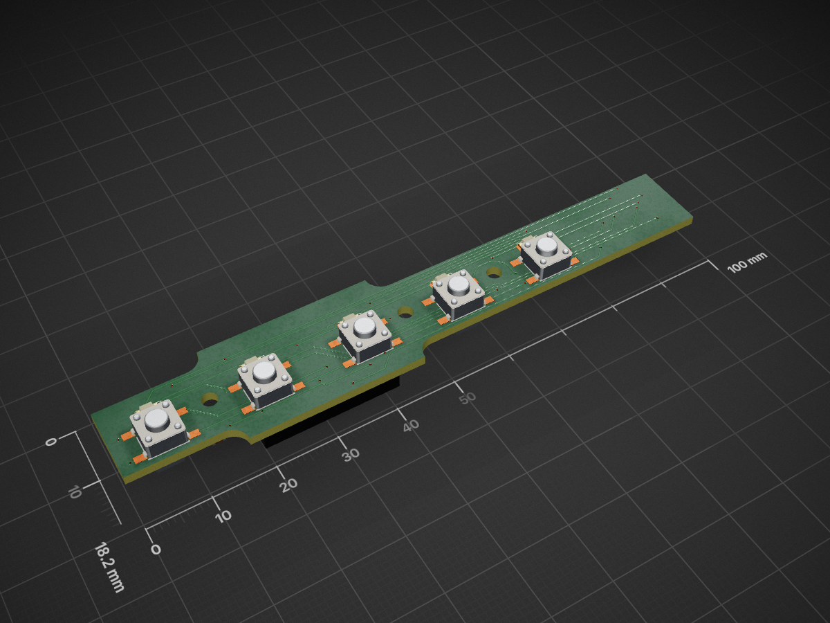
Knappepanel flexit is an open-source printed circuit board by KrHaaland, from the KrHaaland/Flexit-Button-controller repository on GitHub. It is a 2-layer board of 100 × 18.2 mm with 26 parts on 30 nets, routed with 343 tracks and 42 vias.
It is built around the AQY212S. Its parts include 6 ICs, 5 resistors, 5 diodes, 5 switches and 2 capacitors. It belongs with the home automation and IoT and radio and wireless boards and the ESP32 and RISC-V boards of this library.
ESP32-C5 button panel for the Flexit Tradition-S ventilation unit. Replaces or parallels the original 5-button control panel with an isolated emulator that adds Wi-Fi (2.4 GHz + 5 GHz) and MQTT for smart-home integration.
The ESP32-C5 is currently one of the few cheap ESP modules with dual-band Wi-Fi 6, which lets the panel live on either band depending on your home network and signal coverage.
The board exposes 5 channels, each mirroring one button + indicator LED on the original Flexit Tradition-S panel:
You get three ways to interact with the panel:
PCB/ (Gerbers/BOM/positions for the fab in PCB/production/).FW/ESP32-C5-Flexit/src/main.cpp)| Channel | Trigger out | LED in |
|---|---|---|
| 1 | IO6 | IO4 |
| 2 | IO7 | IO3 |
| 3 | IO8 | IO2 |
| 4 | IO9 | IO1 |
| 5 | IO10 | IO5 |
Board revision matters: the table above is board rev 2 (all LED inputs on ADC-capable pins). The original rev-1 board wired LEDs to IO5–IO9 and triggers to IO4–IO0 — firmware ≤ 0.2.x fits rev 1 only, firmware ≥ 0.3.0 fits rev 2 only. Flashing the wrong pairing drives the opto-couplers from pins wired to LED sense lines.
Trigger outputs idle LOW and pulse HIGH for ~300 ms (configurable from the UI) to emulate a press.
Board rev 2 routes all five LED inputs onto IO1–IO5 — the only pins the ESP32-C5's SAR ADC reaches — so every LED is read as analog. An unlit LED doesn't conduct, which would leave its sense line floating — out of spec for the ADC (the C5 datasheet characterizes it with a 100 nF cap on the input) and the source of wildly wandering readings during bring-up. The firmware therefore keeps the internal ~45 kΩ pulldown enabled on every sense line (re-enabled after ADC attach, which turns digital pulls off): an unlit line reads a solid 0, while a lit line sits at ~460 counts (≈1.5 V — the LED's forward voltage; its mA-scale drive is unaffected by the pulldown). Each line is sampled with a short ADC burst every ~100 ms (first sample discarded for mux settling). Classification is two-layered: a windowed minimum over ~10 s with hysteresis (280/320 counts) as the safety net, plus a fast path — a floor reading means UNLIT immediately, and a reading at lit level while another line just showed the floor means LIT immediately — so both transitions normally report within ~0.2–0.5 s. Known trade-off: the Flexit occasionally biases an unlit line to ~V_f for a few seconds (invisible µA through the LED), which the fast path reports as a short lit blip; debounce sub-5 s pulses in automations if that matters. /status exposes "adc" (windowed min per channel) and "raw" (last burst); /adcsolo?ch=N samples a single channel for diagnostics (ch=-1 restores round-robin). (readLed() auto-detects which pins are ADC-capable via digitalPinToAnalogChannel(); a pin without ADC would fall back to a digital read.)
Requires PlatformIO (pip install platformio or the VSCode extension).
cd FW/ESP32-C5-Flexit
pio run                       # compile
pio run -t upload             # flash via USB-C
pio device monitor -b 115200  # serial log
The C5 enumerates as /dev/ttyACM* (built-in USB Serial JTAG, no driver needed).
Flexit-Setupfibonacci (default; the Wi-Fi form lets you set a custom one if you don't want the documented value).http://flexit.local/ via mDNS).flexit.local.Wi-Fi credentials and the AP-password override are stored in NVS and survive a reflash. Forget & reboot to AP wipes the Wi-Fi creds but keeps the AP password override.
If the home network is briefly unreachable at boot, the board lands in AP mode but periodically retries (every 5 min) so a transient router outage doesn't strand it.
| Section | What it does |
|---|---|
| Knapper | 5 trigger buttons + 5 live LED indicators (polled every 400 ms). |
| Pulse duration | Length of the simulated button press (20–2000 ms, default 300 ms). Useful if a Flexit function requires a long-press. |
| MQTT | Broker host/port, optional user/password, base topic, heartbeat republish interval, live connection status, MAC-derived client ID. |
| Wi-Fi | SSID + password, Save & reboot into STA, Forget clears creds. Banner at top shows current STA/AP state, RSSI, IP. |
Everything except Wi-Fi changes applies live without reboot.
Everything the web UI does goes through these endpoints, so they can be scripted directly:
| Endpoint | Method | What it does |
|---|---|---|
/status | GET | JSON: leds (0/1 ×5), pulses (active ×5), adc (windowed-min counts ×5), raw (last burst ×5). |
/trigger | POST | sw=1..5 — fire a button pulse. Rejected with 503 while an OTA upload is running. |
/config | GET/POST | Pulse duration (pulseMs=20..2000), persisted in NVS. |
/mqtt | GET/POST | host, port, user, pass, base (topic prefix), pubIntervalSec (heartbeat). |
/wifi | POST | ssid, pass (+ optional apPass fallback override) — saves and reboots into STA. |
/wifi/clear | POST | Forget Wi-Fi credentials, reboot to setup AP. |
/netinfo | GET | Current mode (STA/AP), SSID, IP, RSSI. |
/version | GET | FW version, build timestamp, SDK, chip, flash size, free heap/slot. |
/update | POST | Multipart firmware.bin upload (OTA) + reboot. |
/adcsolo | GET | Diagnostic: ch=0..4 samples only that LED channel (others untouched), ch=-1 restores round-robin. |
When the board is in STA mode (joined to your Wi-Fi) and a broker host is configured, it connects to the broker and stays connected with auto-reconnect and a Last Will. With base topic flexit (default — configurable in the UI):
| Topic | Direction | Payload | Notes |
|---|---|---|---|
flexit/led/1..5/state | publish | ON / OFF | Retained. Sent on every transition; also republished periodically if heartbeat > 0. |
flexit/sw/1..5/trigger | subscribe | any (optional <ms>) | Any payload triggers a pulse on that channel. A numeric payload overrides the configured pulse duration for that single trigger. |
flexit/status | publish | online / offline | LWT, retained. |
Client ID is flexit-<MAC> (12 hex chars from the chip's eFuse MAC) — globally unique per ESP32. Use it in your broker's ACL.
mqtt:
  binary_sensor:
    - name: "Flexit LED 1"
      state_topic: "flexit/led/1/state"
      payload_on: "ON"
      payload_off: "OFF"
    # ... repeat for 2..5
  button:
    - name: "Flexit button 1"
      command_topic: "flexit/sw/1/trigger"
# ... repeat for 2..5Once the device is on your Wi-Fi (STA mode), you don't need USB again — there are two ways to push a new build:
cd FW/ESP32-C5-Flexit && pio run. The artifact is .pio/build/esp32-c5-devkitc1-n4/firmware.bin.http://flexit.local/ or its STA IP).firmware.bin, click Upload & reboot. The progress bar tracks the upload, then the board reboots into the new image. The page auto-reloads after ~8 s.cd FW/ESP32-C5-Flexit
pio run -e esp32-c5-devkitc1-n4-ota -t uploadThis uses the espota protocol over mDNS at flexit.local:3232.
Switched from the Arduino default (default.csv, 1.25 MB per app slot) to min_spiffs.csv (1.875 MB per slot, two slots, plus 128 KB SPIFFS). NVS stays at offset 0x9000 so saved Wi-Fi / MQTT / pulse settings survive the migration when you flash the OTA-enabled image for the first time.
The HTTP OTA path is hardened against the common failure modes:
/trigger + MQTT-fired triggers are ignored during the upload — a press in flight can't keep the opto-coupler latched through the multi-second multipart parse.Update.begin, a short write, or Update.end reports an error — no point in streaming 1 MB just to fail at the end.offline retained to <base>/status and disconnects gracefully before the reboot, so subscribers see the flap immediately instead of waiting out the 30 s keepalive.server.close() + an 800 ms settle before ESP.restart() give the TCP FIN and the HTTP 200 response enough time to flush on a marginal link.There's no authentication on either OTA path or on the other config endpoints. The assumption is that your Wi-Fi LAN is trusted (this is a home device behind your router, not on the open internet). Anyone with route to the device on TCP 80 or 3232 can re-flash it.
The AP fallback PSK is fibonacci by default — yes, the same one this README mentions, on purpose. The Wi-Fi form lets you override it per device if you'd rather not advertise it in the source. Override is persisted in NVS.
If you need stricter controls (HTTP Basic auth on /update, an ArduinoOTA password, signed firmware images, broker ACLs, VLANs), open an issue.
.
├── FW/ESP32-C5-Flexit/      PlatformIO project (Arduino framework)
│   ├── src/main.cpp         Firmware
│   └── src/index_html.h     Embedded web UI (single page)
├── PCB/                     KiCad schematic + PCB design
│   └── production/          Gerbers, BOM, positions for fab
└── knappepanel_flexit.kicad_proMSPI Timing: Failed to allocate dummy cacheline for PSRAM memory barrier! — harmless, the C5-Mini has no PSRAM but the SDK looks for it.LED_ACTIVE_HIGH in src/main.cpp).No license set yet — treat as "all rights reserved" until one is added. Open an issue if you'd like a specific one (MIT / Apache-2.0 / CC-BY-SA for the hardware, etc.).
| Qty | Value | Footprint | References |
|---|---|---|---|
| 5 | AQY212S | Kicad8_multilib:AQY212S | U1, U2, U3, U4, U5 |
| 5 | LED | LED_SMD:LED_1206_3216Metric | D1, D2, D3, D4, D5 |
| 5 | R | Resistor_SMD:R_0805_2012Metric | R1, R2, R3, R4, R5 |
| 5 | Tactile SW 6x6mm | Kicad8_multilib:Tactile SW 6x6mm | SW1, SW2, SW3, SW4, SW5 |
| 2 | 10uF | Capacitor_SMD:C_0805_2012Metric | C1, C2 |
| 2 | TestPoint | TestPoint:TestPoint_Pad_1.5x1.5mm | TP1, TP2 |
| 1 | MicroMatch_2x6 | Kicad8_multilib:Micromatch_2x6 | J1 |
| 1 | ~ | Kicad8_multilib:ESP32-C5Mini | U7 |
It measures 100 × 18.2 mm and has 2 copper layers, 1.6 mm thick.
26 parts, built around the AQY212S. The full list of its parts is on this page, with links to each part's symbol and footprint where PCBKit's library has them.
From the KrHaaland/Flexit-Button-controller repository on GitHub, at the commit this page was made from: the board is PCB/knappepanel_flexit.kicad_pcb and its schematic FW/ESP32-C5-Flexit/knappepanel_flexit.kicad_sch. PCBKit opens the board in the browser, with nothing to install.
Its repository states no licence, so its author keeps all rights: ask KrHaaland before reusing the design.

nsm81/VehiclePrecharge_PCB
The precharge board contains the precharge resistors, precharge relay, main relay drivers (with economisers), and a controlling micro.

samba09/camper-pir-switch
PIR motion switch for Revotion NODE Ambient (AM312, PhotoMOS, KiCad)


hackclub/OnBoard
💡 Join 1,000 teenagers and make your first PCB with a $100 grant!

