2 layers85 × 56 mm
Yoga v2
mschwingen/hardware
Hardware designs by Michael Schwingen, michael at schwingen dot org
85 parts10
 krebsd/current-diffamp
Differential Amplifier circuit for use in current sensing applications. The circuit is designed to be used in conjunction with an oscilloscope.
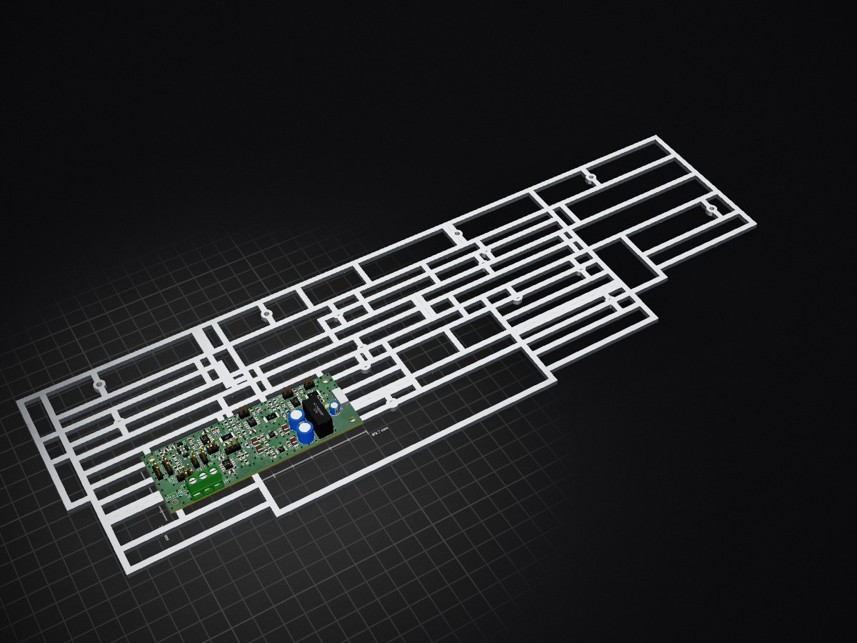
DiffAmp is an open-source printed circuit board by krebsd, from the krebsd/current-diffamp repository on GitHub, published under the CC-BY-SA-4.0 licence. It is a 2-layer board of 99.7 × 35.6 mm with 274 parts on 62 nets, routed with 725 tracks and 22 vias.
It is built around the OPA189ID, AD8421ARZ and CMPD6001S, with the PFRA.050.2 and Y14870R10000B9W among its other parts. Its parts include 43 resistors, 39 capacitors, 7 ICs, 5 connectors and 4 diodes.


Differential Amplifier circuit for use in current sensing applications. The circuit is designed to be used in conjunction with an oscilloscope.
This project and especially its documentation including this README is still in a very early state of development. This document will be updated with further information in the future.

This work is licensed under a Creative Commons Attribution-ShareAlike 4.0 International License
| Qty | Value | Footprint | References |
|---|---|---|---|
| 163 | DiffAmp:VIA-0.6mm | , , , , , , , , , , , , , , , +147 | |
| 12 | C | Capacitors_SMD:C_0805 | C15, C16, C17, C18, C19, C20, C23, C24, C25, C29, C34, C39 |
| 11 | 100n | Capacitors_SMD:C_0805 | C2, C14, C26, C27, C28, C31, C32, C33, C36, C37, C38 |
| 8 | 249 | Resistors_SMD:R_0805 | R19, R20, R21, R22, R23, R24, R25, R26 |
| 5 | 10n | Capacitors_SMD:C_0805 | C7, C8, C9, C10, C13 |
| 4 | 0 | Resistors_SMD:R_0805 | R5, R29, R34, R40 |
| 4 | 10k | Resistors_SMD:R_0805 | R2, R3, R7, R8 |
| 4 | 10u | Capacitors_SMD:C_1210 | C5, C6, C11, C12 |
| 4 | 3M9 | Resistors_SMD:R_0805 | R11, R12, R13, R14 |
| 4 | CMPD6001S | TO_SOT_Packages_SMD:SOT-23 | D1, D2, D3, D4 |
| 4 | Jumper_NC_Dual | Pin_Headers:Pin_Header_Straight_1x03_Pitch2.54mm | JP1, JP3, JP6, JP7 |
| 3 | 47 | Resistors_SMD:R_2512 | R30, R36, R42 |
| 3 | Conn_01x02 | Pin_Headers:Pin_Header_Straight_1x02_Pitch2.54mm | J3, J4, J5 |
| 3 | Jumper | Pin_Headers:Pin_Header_Straight_1x02_Pitch2.54mm | JP2, JP4, JP5 |
| 3 | OPA189 | Housings_SOIC:SOIC-8_3.9x4.9mm_Pitch1.27mm | U4, U6, U7 |
| 3 | R | Resistors_SMD:R_0805 | R31, R37, R43 |
| 2 | 100u | Capacitors_THT:CP_Radial_D8.0mm_P3.50mm | C3, C4 |
| 2 | 10p | Capacitors_SMD:C_0805 | C30, C35 |
| 2 | 130k | Resistors_SMD:R_0805 | R1, R4 |
| 2 | 1M0 | Resistors_SMD:R_0805 | R17, R18 |
| 2 | 1M2 | Resistors_SMD:R_0805 | R15, R16 |
| 2 | 1k | Resistors_SMD:R_0805 | R6, R28 |
| 2 | 1k0 | Resistors_SMD:R_0805 | R32, R38 |
| 2 | 2k2 | Resistors_SMD:R_0805 | R35, R41 |
| 2 | 6k8 | Resistors_SMD:R_0805 | R33, R39 |
| 2 | C_Variable | Capacitors_SMD:C_Trimmer_Murata_TZC3 | C21, C22 |
| 1 | 100 | Resistors_SMD:R_0805 | R27 |
| 1 | 10u | Capacitors_THT:CP_Radial_D5.0mm_P2.00mm | C1 |
| 1 | 22 | Resistors_SMD:R_0805 | R9 |
| 1 | AD8421 | Housings_SOIC:SOIC-8_3.9x4.9mm_Pitch1.27mm | U5 |
| 1 | Jumper_NO | Pin_Headers:Pin_Header_Straight_1x02_Pitch2.54mm | JP8 |
| 1 | PFRA050 | DiffAmp:R_Axial_DIN0204_L3.6mm_D1.6mm_P5.08mm_Horizontal | F1 |
| 1 | SF_IHXXXXS | Converters_DCDC_ACDC:DCDC-Conv_TRACO_TMR_1-xxxx_Dual | U1 |
| 1 | Screw_Terminal_1x03 | Connectors_Terminal_Blocks:TerminalBlock_bornier-3_P5.08mm | J2 |
| 1 | TPS7A30 | Housings_SSOP:MSOP-8-1EP_3x3mm_Pitch0.65mm | U3 |
| 1 | TPS7A49 | Housings_SSOP:MSOP-8-1EP_3x3mm_Pitch0.65mm | U2 |
| 1 | USB_OTG | DiffAmp:MIC_USB_BBU | J1 |
| 1 | Y14870R10000B9W | DiffAmp:CSM2512 | R10 |
The 270 most common of 274 parts.
It measures 99.7 × 35.6 mm and has 2 copper layers, 1.6 mm thick.
274 parts, built around the OPA189ID, AD8421ARZ, CMPD6001S and PFRA.050.2. The full list of its parts is on this page, with links to each part's symbol and footprint where PCBKit's library has them.
From the krebsd/current-diffamp repository on GitHub, at the commit this page was made from: the board is DiffAmp.kicad_pcb. PCBKit opens the board in the browser, with nothing to install.
Its repository publishes it under the CC-BY-SA-4.0 licence: you may reuse it on that licence's terms (keep the author's notice, and for a copyleft licence share your changes alike).
mschwingen/hardware
Hardware designs by Michael Schwingen, michael at schwingen dot org

JQIamo/PI_wt_hold_for_laser_intensity_lock
PI controller with integrator hold control for laser intensity lock.


kuon/pcb-ucurrent
My PCB for µcurrent board https://www.eevblog.com/projects/ucurrent/

Pgr18/CELL_Z_SPECT_hardware
Печатные платы для проекта клеточной импедансной спектроскопии

TobiasNetzer/nanoLogger
Here is a simplified block diagram of the data logger. To measure the current of a device, the data logger is simply connected in series between the voltage source and the DUT/load.