2 layers115 × 115 mm
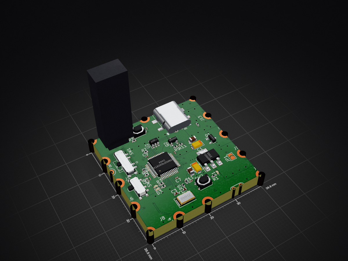
 kramxkomitus/LED_PCB
LED PCB is an open-source printed circuit board by kramxkomitus, from the kramxkomitus/LED_PCB repository on GitHub. It is a 4-layer board of 39.8 × 39.8 mm with 187 parts on 125 nets, routed with 816 tracks and 111 vias.
It is built around the AMS1117-3.3, WS2812B and BSS138, with the SI2319CDS among its other parts. Its parts include 77 capacitors, 67 diodes, 18 connectors, 14 resistors and 4 switches. It belongs with the STM32 boards of this library.


| Qty | Value | Footprint | References |
|---|---|---|---|
| 71 | 100n | Capacitor_SMD:C_0201_0603Metric | C10, C11, C12, C13, C14, C15, C16, C17, C18, C19, C20, C21, C22, C23, C24, C25 +55 |
| 64 | WS2812B | LED_PCB_LIB:LED-2020 | D10, D11, D12, D13, D14, D15, D16, D17, D18, D19, D20, D21, D22, D23, D24, D25 +48 |
| 6 | 10k | Resistor_SMD:R_0402_1005Metric | R6, R7, R8, R9, R10, R14 |
| 4 | +5v Pad | MountingHole:MountingHole_2.2mm_M2_DIN965_Pad_TopOnly | J1, J2, J3, J4 |
| 4 | 1.5k | Resistor_SMD:R_0402_1005Metric | R1, R2, R3, R4 |
| 4 | GND Pad | MountingHole:MountingHole_2.2mm_M2_DIN965_Pad_TopOnly | J5, J6, J7, J8 |
| 2 | 22u t | Capacitor_SMD:C_0805_2012Metric | C2, C5 |
| 2 | 30p | Capacitor_SMD:C_0402_1005Metric | C3, C4 |
| 2 | 4.7u | Capacitor_Tantalum_SMD:CP_EIA-3216-12_Kemet-S | C1, C76 |
| 2 | 5.1k | Resistor_SMD:R_0402_1005Metric | R12, R13 |
| 2 | SW_reset | Button_Switch_SMD:SW_Push_1P1T_NO_Vertical_Wuerth_434133025816 | SW2, SW4 |
| 1 | 1k5 | Resistor_SMD:R_0402_1005Metric | R11 |
| 1 | 4.7M | Resistor_SMD:R_0402_1005Metric | R5 |
| 1 | 8MHz | Crystal:Crystal_SMD_5032-2Pin_5.0x3.2mm | Y1 |
| 1 | AMS1117-3.3 | Package_TO_SOT_SMD:SOT-223-3_TabPin2 | U1 |
| 1 | BSS138 | Package_TO_SOT_SMD:SOT-23 | Q2 |
| 1 | Blue | LED_SMD:LED_0402_1005Metric | D2 |
| 1 | ENA_pad | TestPoint:TestPoint_Keystone_5000-5004_Miniature | J18 |
| 1 | EXT_SIGNAL | Jumper:SolderJumper-2_P1.3mm_Open_TrianglePad1.0x1.5mm | JP1 |
| 1 | LED_MATRIX_IN | MountingHole:MountingHole_2.2mm_M2_DIN965_Pad_TopOnly | J15 |
| 1 | Matrix_pad | MountingHole:MountingHole_2.2mm_M2_DIN965_Pad_TopOnly | J16 |
| 1 | Red | LED_SMD:LED_0402_1005Metric | D3 |
| 1 | ST-Link Tagcon | Connector:Tag-Connect_TC2030-IDC-NL_2x03_P1.27mm_Vertical | J9 |
| 1 | STM32F103C8Tx | Package_QFP:LQFP-48_7x7mm_P0.5mm | U3 |
| 1 | SW_DP3T | LED_PCB_LIB:SW_SP3T_PCM13 | SW1 |
| 1 | SW_DPDT_x2 | Button_Switch_SMD:SW_SPDT_PCM12 | SW3 |
| 1 | Si2319CDS | Package_TO_SOT_SMD:SOT-23 | Q1 |
| 1 | TPD4EUSB30 | Package_TO_SOT_SMD:SOT-23-6 | U2 |
| 1 | UART Bottom (TX) | MountingHole:MountingHole_2.2mm_M2_DIN965_Pad_TopOnly | J12 |
| 1 | UART Debug | TestPoint:TestPoint_2Pads_Pitch2.54mm_Drill0.8mm | J10 |
| 1 | UART Left (RX) | MountingHole:MountingHole_2.2mm_M2_DIN965_Pad_TopOnly | J13 |
| 1 | UART Right (TX) | MountingHole:MountingHole_2.2mm_M2_DIN965_Pad_TopOnly | J14 |
| 1 | UART Top (RX) | MountingHole:MountingHole_2.2mm_M2_DIN965_Pad_TopOnly | J11 |
| 1 | USB_C_Receptacle_USB2.0 | LED_PCB_LIB:USB_C_Connector_16P_SMD | J17 |
| 1 | Yellow | LED_SMD:LED_0402_1005Metric | D1 |


danielortval/RamRacing-EV-PCBs
Full schematic and PCB designs for RAM Racing’s Formula SAE Electric Vehicle. Includes tractive system active light, hard fault latch, precharge/discharge circuits, and the complete EV schematic.

malik019/horloge-accelerometer
Een compact, ultra-low-power PCB-ontwerp in KiCad voor een klok (horloge). Maakt gebruik van een ATtiny MCU, een ST LIS2DW12 accelerometer voor bewegingsdetectie en WS2812B-MINI RGB-leds

PhilipMcGaw/robot-NautiPi
NautiPi is the physical hardware and embedded-project repository for the robot projects. It contains electronics, PCB and KiCad work, Arduino projects, component records, mechanical references, photographs, and retained…


OpenLaundry/wifi-rfid-uhf-reader
Portable long range RFID uhf reader with WIFI based on esp32
It measures 39.8 × 39.8 mm and has 4 copper layers, 4.69 mm thick.
187 parts, built around the AMS1117-3.3, WS2812B, BSS138 and SI2319CDS. The full list of its parts is on this page, with links to each part's symbol and footprint where PCBKit's library has them.
From the kramxkomitus/LED_PCB repository on GitHub, at the commit this page was made from: the board is LED_PCB.kicad_pcb and its schematic LED_PCB.kicad_sch. PCBKit opens the board in the browser, with nothing to install.
Its repository states no licence, so its author keeps all rights: ask kramxkomitus before reusing the design.