
4 layers125 × 150 mm
AA2380V1
OneAudio/OSVA
Open source versatible analyzer (24bits 1.536MSPS 2 Channels)
440 parts11GPL-3.0
 kpezeshki/AudioInterfaceLockIn
A script for lock-in measurement using a Motu M2 audio interface
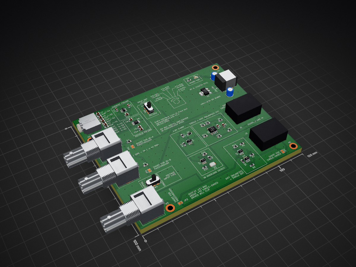
Preamp board is an open-source printed circuit board by kpezeshki, from the kpezeshki/AudioInterfaceLockIn repository on GitHub. It is a 4-layer board of 120 × 100 mm with 70 parts on 48 nets, routed with 350 tracks and 248 vias.
It is built around the AD8221AR and OPA1632D. Its parts include 27 resistors, 14 capacitors, 9 ICs, 6 connectors and 3 diodes. It belongs with the audio and music and interfaces and adapters boards of this library.
A basic dual-phase lockin implementation for a 2in/2out sound card or audio interface using pyaudio. Tested on a MOTU M2 at 32bits/48kHz sample rate under ALSA.
Connect CH1 OUT to CH1 IN through a loopback wire and set gains appropriately. CH2 OUT should be the input to the DUT and CH2 IN should be the output of the DUT.
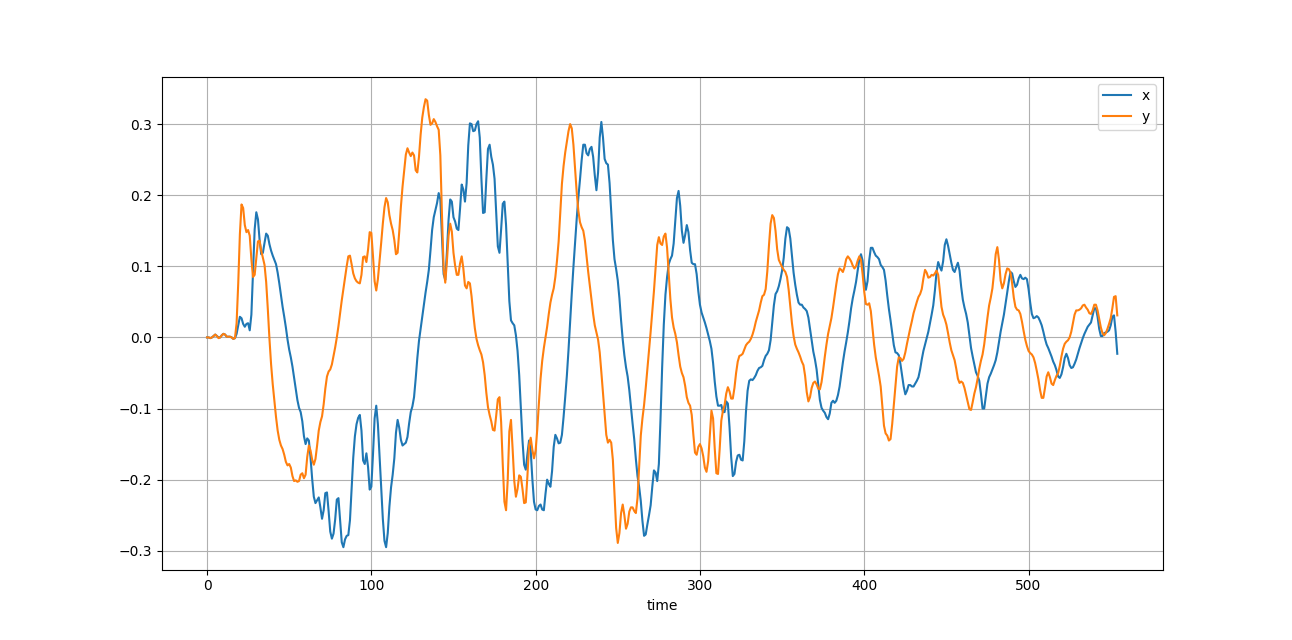
Example output file is log_movemic.txt. This was a simple experiment in which CH2 OUT was connected to a speaker, and CH2 IN connected to a microphone. The microphone was moved away from the speaker at a near-constant rate, and the resulting zero-crossings in the logfile occur when the reference signal and input are out of phase. The physical distance the microphone moves between zeroes provides the speed of sound.
Current problems:
| Qty | Value | Footprint | References |
|---|---|---|---|
| 9 | 100nF | Capacitor_SMD:C_0805_2012Metric_Pad1.18x1.45mm_HandSolder | C3, C4, C5, C8, C9, C11, C12, C13, C14 |
| 9 | 1k | Resistor_SMD:R_0805_2012Metric_Pad1.20x1.40mm_HandSolder | R4, R5, R6, R7, R8, R9, R10, R11, R25 |
| 5 | Jumper_2_Open | Jumper:SolderJumper-2_P1.3mm_Open_TrianglePad1.0x1.5mm | JP2, JP3, JP4, JP5, JP6 |
| 5 | OPA990 | Package_TO_SOT_SMD:SOT-23-6_Handsoldering | U2, U3, U4, U6, U9 |
| 4 | 390 | Resistor_SMD:R_0805_2012Metric_Pad1.20x1.40mm_HandSolder | R13, R14, R15, R16 |
| 4 | MountingHole_Pad | MountingHole:MountingHole_3.2mm_M3_DIN965_Pad | H1, H2, H3, H4 |
| 3 | 100 | Resistor_SMD:R_0805_2012Metric_Pad1.20x1.40mm_HandSolder | R1, R2, R12 |
| 3 | Conn_Coaxial | Connector_Coaxial:BNC_Amphenol_B6252HB-NPP3G-50_Horizontal | J1, J2, J3 |
| 2 | 50 | Resistor_SMD:R_0805_2012Metric_Pad1.20x1.40mm_HandSolder | R19, R24 |
| 2 | 500 | Resistor_SMD:R_0805_2012Metric_Pad1.20x1.40mm_HandSolder | R20, R23 |
| 2 | 50k | Resistor_SMD:R_0805_2012Metric_Pad1.20x1.40mm_HandSolder | R18, R21 |
| 2 | 5k | Resistor_SMD:R_0805_2012Metric_Pad1.20x1.40mm_HandSolder | R17, R22 |
| 2 | AudioJack3 | audiohacks:ACJS-MHDR | J5, J6 |
| 2 | C_Polarized | Capacitor_THT:CP_Radial_D5.0mm_P2.50mm | C1, C2 |
| 1 | 100pF | Capacitor_SMD:C_0805_2012Metric_Pad1.18x1.45mm_HandSolder | C7 |
| 1 | 105-SR10010F-25NS | audiohacks:105-SR10010F-25NS | U7 |
| 1 | 10k | Resistor_SMD:R_0805_2012Metric_Pad1.20x1.40mm_HandSolder | R26 |
| 1 | 10nF | Capacitor_SMD:C_0805_2012Metric_Pad1.18x1.45mm_HandSolder | C10 |
| 1 | 1nF | Capacitor_SMD:C_0805_2012Metric_Pad1.18x1.45mm_HandSolder | C6 |
| 1 | 8k | Resistor_SMD:R_0805_2012Metric_Pad1.20x1.40mm_HandSolder | R27 |
| 1 | AD8221 | Package_SO:MSOP-8_3x3mm_P0.65mm | U8 |
| 1 | AZ1117-3.3 | Package_TO_SOT_SMD:SOT-223-3_TabPin2 | U1 |
| 1 | Barrel_Jack_MountingPin | Connector_BarrelJack:BarrelJack_CUI_PJ-063AH_Horizontal | J4 |
| 1 | D_Zener | Diode_SMD:D_SOD-323_HandSoldering | D2 |
| 1 | LED | LED_THT:LED_D3.0mm | D3 |
| 1 | LED | LED_SMD:LED_0805_2012Metric_Pad1.15x1.40mm_HandSolder | D1 |
| 1 | OPA1632 | Package_SO:SOIC-8_3.9x4.9mm_P1.27mm | U5 |
| 1 | R | Resistor_SMD:R_0805_2012Metric_Pad1.20x1.40mm_HandSolder | R3 |
| 1 | SW_Push_DPDT | Button_Switch_THT:SW_E-Switch_EG1271_DPDT | SW2 |
| 1 | SW_SPST | Button_Switch_THT:SW_E-Switch_EG1271_DPDT | SW1 |
OneAudio/OSVA
Open source versatible analyzer (24bits 1.536MSPS 2 Channels)


NSLS2/zupsc-hw
Zynq UltraScale Power Supply Controller hardware

WAFFLE-Systems/PEC_Sensor
Electrical schematics and PCB gerber files for the Pulsed Eddy Current Sensor

akshmakov/utcs-isource
micro-transcranial current stimulation system - constant current source module


Open-Smartwatch/open-smartwatch-gps
Hardware design files for the GPS version of the open-smartwatch
It measures 120 × 100 mm and has 4 copper layers, 4.69 mm thick.
70 parts, built around the AD8221AR and OPA1632D. The full list of its parts is on this page, with links to each part's symbol and footprint where PCBKit's library has them.
From the kpezeshki/AudioInterfaceLockIn repository on GitHub, at the commit this page was made from: the board is preamp_board/preamp_board.kicad_pcb and its schematic preamp_board/-1v_clamp.kicad_sch. PCBKit opens the board in the browser, with nothing to install.
Its repository states no licence, so its author keeps all rights: ask kpezeshki before reusing the design.