2 layers80 × 65 mm

 balmerdx/RLCMeterH75026
Good RLC meter
RLCMeterH750 v2 is an open-source printed circuit board by balmerdx, from the balmerdx/RLCMeterH750 repository on GitHub. It is a 2-layer board of 80 × 65 mm with 161 parts on 173 nets, routed with 1,176 tracks and 266 vias.
It is built around the AD8031AN, AD8221AR and LTC1550LCS8-2#PBF, with the FSA3357L8X, HT7333 and AD9833BRM among its other parts. Its parts include 67 capacitors, 58 resistors, 20 ICs, 4 connectors and 4 inductors. It belongs with the STM32 boards of this library.


Это RLC построенный на STM32H750. Основные отличительные особенности:
Про точность не буду сильно распинаться, ибо сам точно не знаю. Но приблизительно опишу. Сопротивления измеряются в диапазоне от единиц миллиом до сотен килоом. Но десятые доли пикофарада без проблемм можно измерить. На частотах 100 КГц и выше. Десятки наногенри тоже вполне можно измерять. Тоже на высоких частотах, но тут желательно теорию подучить, чтобы понимать что измеряется. На низких частотах вполне можно измерять десятки милифарад и единицы генри.
И да, внимание!!!! Финальной PCB нет в этом проекте. На плату RLCMeterH750_v2 я вкорячил детали от схемы RLCMeterH750_v3. Собственно говоря вариант RLCMeterH750_v2 тоже полностью рабочий, но он имеет отвратительно большие ошибки на частотах ниже 300 Гц. RLCMeterH750_v3 исправляет резонансы, которые были не учтены мной.
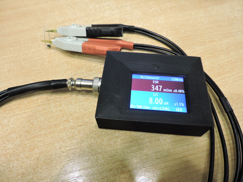
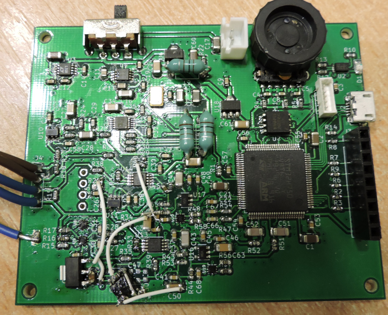
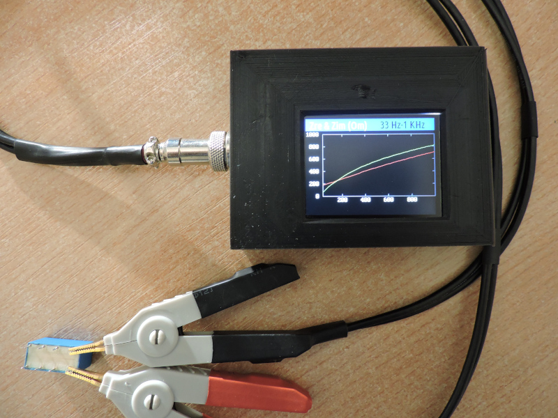
А ещё этот RLC измеритель умеет строить графики значений в зависимости от частоты. Вот пример измерения катушки индуктивности от реле. Красная линия - вещественная часть сопротивления, зелёная - мнимая часть сопротивления. Естественно железный сердечник ведёт себя совсем не так, как хорошая катушка индуктивности.
| Qty | Value | Footprint | References |
|---|---|---|---|
| 35 | 100n | Capacitor_SMD:C_0603_1608Metric | C3, C10, C12, C14, C18, C19, C20, C22, C25, C32, C33, C35, C36, C37, C38, C39 +19 |
| 18 | 1k | Resistor_SMD:R_0603_1608Metric | R10, R16, R18, R19, R21, R23, R26, R34, R35, R37, R38, R39, R40, R44, R46, R48 +2 |
| 11 | 10k | Resistor_SMD:R_0603_1608Metric | R4, R5, R11, R14, R17, R33, R36, R41, R42, R57, R58 |
| 11 | 33 | Resistor_SMD:R_0603_1608Metric | R2, R3, R6, R7, R8, R9, R29, R30, R31, R32, R49 |
| 10 | 10u | Capacitor_SMD:C_1206_3216Metric | C1, C2, C7, C15, C16, C17, C21, C27, C28, C60 |
| 7 | 22n | Capacitor_SMD:C_0603_1608Metric | C4, C5, C8, C30, C31, C66, C67 |
| 5 | 100u | Capacitor_SMD:C_1206_3216Metric | C24, C50, C61, C63, C64 |
| 5 | AD8031 | Package_TO_SOT_SMD:SOT-23-5 | U10, U11, U15, U16, U17 |
| 4 | 3k | Resistor_SMD:R_0603_1608Metric | R27, R28, R47, R54 |
| 4 | FSA3357L8X | balmer:MicroPak_8-Lead | U8, U9, U19, U20 |
| 3 | 100 | Resistor_SMD:R_0603_1608Metric | R1, R15, R20 |
| 3 | 100uH | Inductor_THT:L_Axial_L5.3mm_D2.2mm_P7.62mm_Horizontal_Vishay_IM-1 | L2, L3, L4 |
| 2 | 1u | Capacitor_SMD:C_0805_2012Metric | C11, C13 |
| 2 | 27k | Resistor_SMD:R_0603_1608Metric | R22, R24 |
| 2 | 330p | Capacitor_SMD:C_1206_3216Metric | C43, C44 |
| 2 | 360 | Resistor_SMD:R_0603_1608Metric | R51, R52 |
| 2 | 510 | Resistor_SMD:R_0603_1608Metric | R43, R45 |
| 2 | 560p | Capacitor_SMD:C_1206_3216Metric | C51, C52 |
| 2 | 68k | Resistor_SMD:R_0603_1608Metric | R53, R55 |
| 2 | AD8221 | Package_SO:MSOP-8_3x3mm_P0.65mm | U13, U14 |
| 2 | HT7333 | Package_TO_SOT_SMD:SOT-89-3 | U6, U18 |
| 1 | 180k | Resistor_SMD:R_0603_1608Metric | R13 |
| 1 | 180p | Capacitor_SMD:C_0603_1608Metric | C29 |
| 1 | 2.2u | Capacitor_SMD:C_0805_2012Metric | C40 |
| 1 | 22k | Resistor_SMD:R_0603_1608Metric | R12 |
| 1 | 25MHz | balmer:Crystal_5.0x3.2mm | U5 |
| 1 | 25u | Capacitor_SMD:C_1206_3216Metric | C34 |
| 1 | 2k | Resistor_SMD:R_0603_1608Metric | R25 |
| 1 | 33p | Capacitor_SMD:C_0603_1608Metric | C26 |
| 1 | 400 mA-h? | Connector_PinSocket_2.54mm:PinSocket_1x02_P2.54mm_Vertical | BT1 |
| 1 | 600Z | Inductor_SMD:L_1206_3216Metric | L1 |
| 1 | AD9833 | Package_SO:MSOP-10_3x3mm_P0.5mm | U12 |
| 1 | DUT | Connector_PinHeader_2.54mm:PinHeader_1x04_P2.54mm_Vertical | J4 |
| 1 | EVQWKL001 | balmer:Encoder_EVQWK4 | SW1 |
| 1 | ILI_9321(2.2inch) | balmer:ILI_9321(2.2inch) | J3 |
| 1 | ISL9204 | balmer:DFN-8-1EP_3x2mm_P0.5mm_EP1.75x1.65mm | U2 |
| 1 | LED | LED_SMD:LED_0805_2012Metric_Pad1.15x1.40mm_HandSolder | D1 |
| 1 | LTC1550LCS8-2 | Package_SO:TSSOP-8_3x3mm_P0.65mm | U3 |
| 1 | M25P16 | Package_SO:SOIC-8_3.9x4.9mm_P1.27mm | U7 |
| 1 | PowerOn | balmer:SW_Angled_with_GND | SW2 |
| 1 | STM32H750VITx | Package_QFP:LQFP-100_14x14mm_P0.5mm | U1 |
| 1 | SWD | Connector_PinSocket_1.27mm:PinSocket_1x05_P1.27mm_Vertical | J1 |
| 1 | TPS60241DGKR | Package_SO:TSSOP-8_3x3mm_P0.65mm | U4 |
| 1 | USB_B_Micro | Connector_USB:USB_Micro-B_Molex-105017-0001 | J2 |
The 157 most common of 161 parts.


paretech/Watson
PCB layout and test results for a simple high dynamic range power meter based on the Analog Devices AD8307 Logarithmic Amplifier.


schenkmi/electronic-projects
misc electronic projects

NSLS2/zupsc-hw
Zynq UltraScale Power Supply Controller hardware

WAFFLE-Systems/PEC_Sensor
Electrical schematics and PCB gerber files for the Pulsed Eddy Current Sensor

akshmakov/utcs-isource
micro-transcranial current stimulation system - constant current source module


kpezeshki/AudioInterfaceLockIn
A script for lock-in measurement using a Motu M2 audio interface
It measures 80 × 65 mm and has 2 copper layers, 1.6 mm thick.
161 parts, built around the AD8031AN, AD8221AR, LTC1550LCS8-2#PBF and FSA3357L8X. The full list of its parts is on this page, with links to each part's symbol and footprint where PCBKit's library has them.
From the balmerdx/RLCMeterH750 repository on GitHub, at the commit this page was made from: the board is circuit/RLCMeterH750_v2/RLCMeterH750_v2.kicad_pcb. PCBKit opens the board in the browser, with nothing to install.
Its repository states no licence, so its author keeps all rights: ask balmerdx before reusing the design.