
2 layers116.8 × 21.9 mm
Schemat
konrad1s/LineFollower-Kwark
Fast LineFollower Robot project. Build on STM32 F7 microcontroller with custom PCB. Software, Hardware and QT Application.
42 parts12MIT

Fast LineFollower Robot project. Build on STM32 F7 microcontroller with custom PCB. Software, Hardware and QT Application.
Schemat is an open-source printed circuit board by konrad1s, from the konrad1s/LineFollower-Kwark repository on GitHub, published under the MIT licence. It is a 4-layer board of 139.7 × 41.3 mm with 74 parts on 84 nets, routed with 537 tracks and 154 vias.
It is built around the LM1117MP-3.3, FTSH-105-01-F-DV-P-TR and JS202011SCQN, with the QT325G-26.000MAHQ-T among its other parts. Its parts include 20 capacitors, 15 resistors, 12 diodes, 10 connectors and 4 ICs. It belongs with the robots and motor control boards and the STM32 boards of this library.


The LineFollower Robot is an autonomous robot designed to follow a predefined path marked by a black or white line.
This project serves a quite advanced solution including hardware project, embedded software and PC QT application.
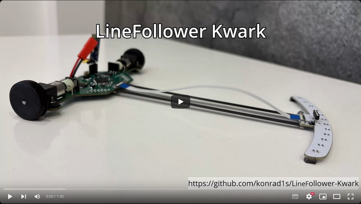
A short video demo is available on YouTube.
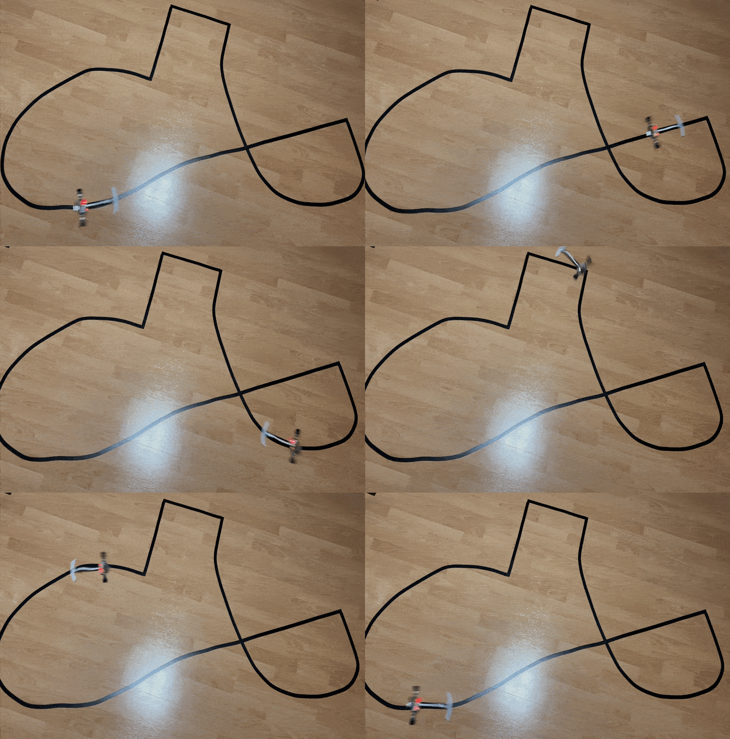
Example - one of the first - linefollower run:
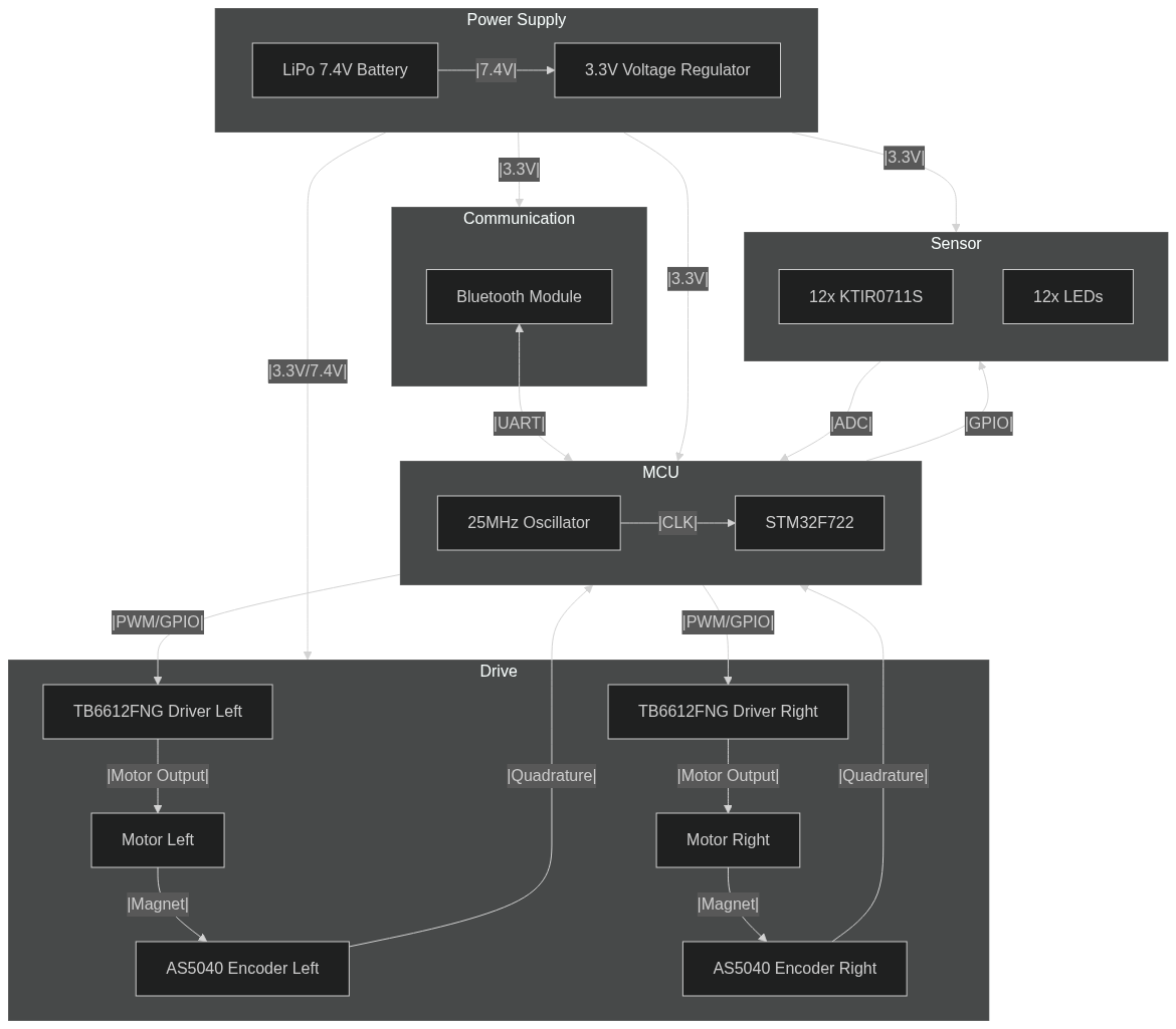
Electronic circuit diagrams are available in the Hardware/release/schematic folder.
Gerbers files are available in the Hardware/release/gerbers folder.
Main board:
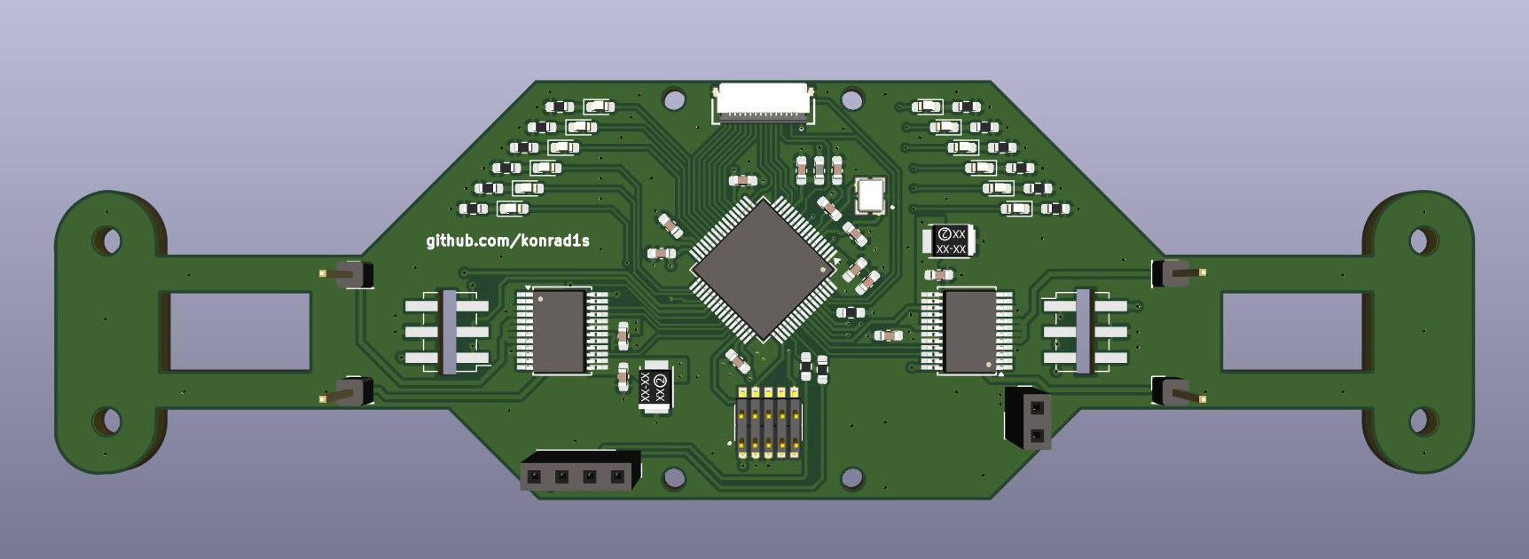
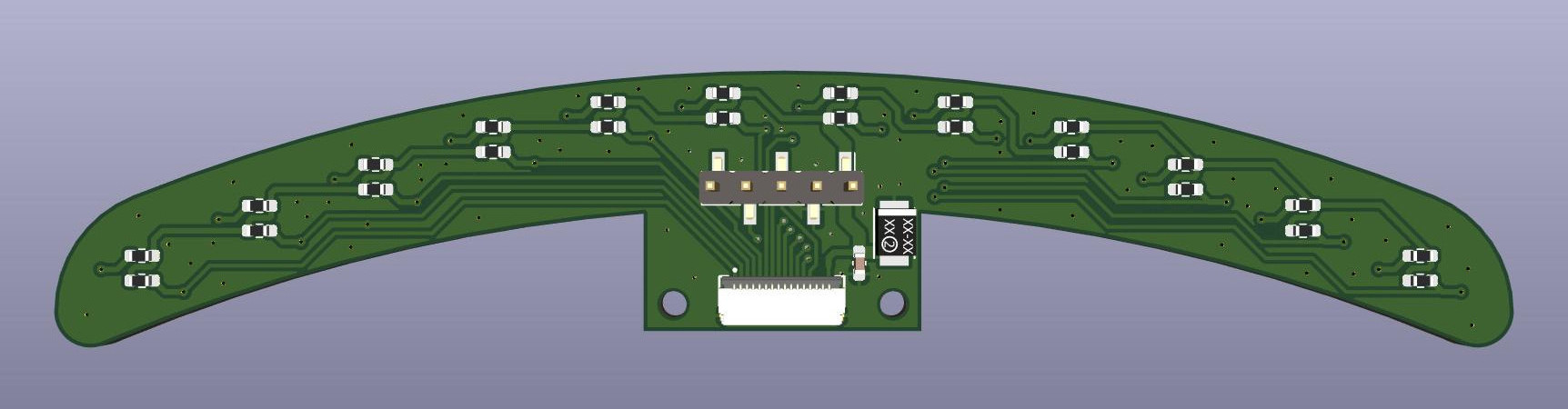
Sensor board:
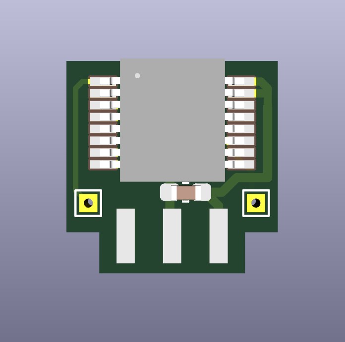
Encoder board:
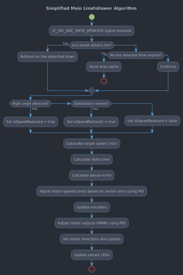
The core functionality is implemented through an event-driven state machine. The primary signal is the LF_SIG_ADC_DATA_UPDATED, which is raised whenever new ADC data is available. Currently every 5ms, however increasing this frequency can lead to better control results.
The activity diagram presents simplified main robot algorithm in RUN state:
Short brief about implemented software components:
Implemented bootloader allows for over the air firmware updates without the need of programmer. This is particularly useful for making quick updates "on the road." The bootloader uses the implemented SCP (Serial Communication Protocol) to receive firmware updates over Bluetooth.
There are 2 methods to enter the Bootloader:
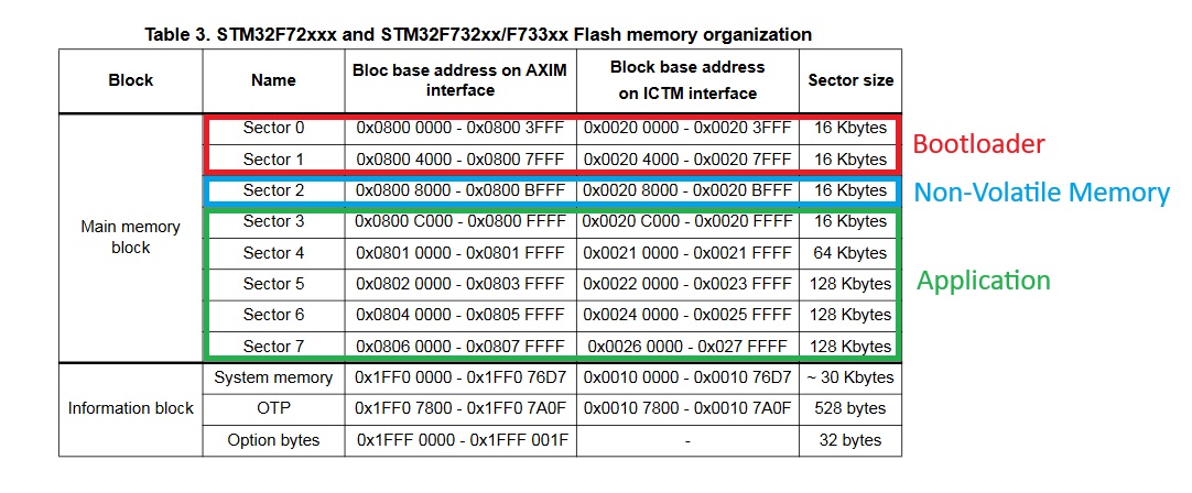
FLASH memory layout:
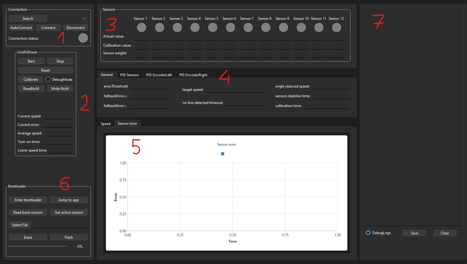
The QT Application provides a graphical interface to control, configure, and monitor the robot. The main sections of the interface and their functionalities are as follows:
| Qty | Value | Footprint | References |
|---|---|---|---|
| 13 | 100nF | Capacitor_SMD:C_0603_1608Metric_Pad1.08x0.95mm_HandSolder | C2, C4, C6, C9, C10, C11, C12, C13, C15, C17, C20, C21, C22 |
| 13 | R | Resistor_SMD:R_0603_1608Metric_Pad0.98x0.95mm_HandSolder | R3, R4, R5, R6, R7, R8, R9, R10, R11, R12, R13, R14, R15 |
| 12 | LED | LED_SMD:LED_0603_1608Metric_Pad1.05x0.95mm_HandSolder | D1, D2, D3, D4, D5, D6, D7, D8, D9, D10, D11, D12 |
| 10 | , , @HOLE0, @HOLE1, @HOLE2, @HOLE3, @HOLE8, @HOLE8, @HOLE9, @HOLE9 | ||
| 4 | 10uF | Capacitor_Tantalum_SMD:CAP_293D-B_VSS | C1, C7, C14, C16 |
| 2 | 10k | Resistor_SMD:R_0603_1608Metric_Pad0.98x0.95mm_HandSolder | R1, R2 |
| 2 | 18pF | Capacitor_SMD:C_0603_1608Metric_Pad1.08x0.95mm_HandSolder | C3, C5 |
| 2 | Conn_Moto1_A | Connector_PinHeader_2.54mm:PinHeader_1x01_P2.54mm_Vertical | J9, J12 |
| 2 | Conn_Moto1_B | Connector_PinHeader_2.54mm:PinHeader_1x01_P2.54mm_Vertical | J10, J13 |
| 2 | TB6612FNG | Package_SO:SSOP-24_5.3x8.2mm_P0.65mm | U3, U4 |
| 1 | 4.7uF | Capacitor_SMD:C_0603_1608Metric_Pad1.08x0.95mm_HandSolder | C8 |
| 1 | Battery | Connector_PinSocket_2.54mm:PinSocket_1x02_P2.54mm_Vertical | J1 |
| 1 | Conn_01x04_Socket | Connector_PinSocket_2.54mm:PinSocket_1x04_P2.54mm_Vertical | J2 |
| 1 | Conn_Encoder1 | Connector_PinHeader_2.54mm:PinHeader_2x03_P2.54mm_Vertical_SMD | J6 |
| 1 | Conn_Encoder2 | Connector_PinHeader_2.54mm:PinHeader_2x03_P2.54mm_Vertical_SMD | J11 |
| 1 | FTSH-105-01-F-DV-P-TR | Connector:SAMTEC_FTSH-105-01-F-DV-P-TR | J4 |
| 1 | JS202011SCQN | schemat:SW_JS202011SCQN | S1 |
| 1 | L | Inductor_SMD:L_0603_1608Metric_Pad1.05x0.95mm_HandSolder | L1 |
| 1 | LM1117MP-3.3 | Package_TO_SOT_SMD:SOT-223-3_TabPin2 | U1 |
| 1 | QT325G-26.000MAHQ-T | Oscillator:XTAL_QT325G-26.000MAHQ-T | Y1 |
| 1 | SENSOR_CONN | Sensor:GCT_FFC2B28-16-G | J3 |
| 1 | STM32F722RETx | Package_QFP:LQFP-64_10x10mm_P0.5mm | U2 |
konrad1s/LineFollower-Kwark
Fast LineFollower Robot project. Build on STM32 F7 microcontroller with custom PCB. Software, Hardware and QT Application.

konrad1s/LineFollower-Kwark
Fast LineFollower Robot project. Build on STM32 F7 microcontroller with custom PCB. Software, Hardware and QT Application.

buckles3636/EasyBLDC
Please ensure your designs meet common standards and include necessary documentation and comments.


BigBroBob2/bat_tag_nrf5340dk
A custom-designed device to record free-flying bat kinematics, echos, and eye movement

zenglhardt/millimobile-platform
This repo contains the KiCad PCB design files for the development board verison of the MilliMobile. For more information on the platform, see the project page


aws/iot-expresslink
This device was designed and created for the AWS IoT ExpressLink Demo Badge Workshop, which was run at re:Invent 2022.

GMUCERG/fobos
Flexible Open-source workBench fOr Side-channel analysis (FOBOS)
It measures 139.7 × 41.3 mm and has 4 copper layers, 1.6 mm thick.
74 parts, built around the LM1117MP-3.3, FTSH-105-01-F-DV-P-TR, JS202011SCQN and QT325G-26.000MAHQ-T. The full list of its parts is on this page, with links to each part's symbol and footprint where PCBKit's library has them.
From the konrad1s/LineFollower-Kwark repository on GitHub, at the commit this page was made from: the board is Hardware/main_pcb/schemat.kicad_pcb and its schematic Hardware/encoder_pcb/schemat.kicad_sch. PCBKit opens the board in the browser, with nothing to install.
Its repository publishes it under the MIT licence: you may reuse it on that licence's terms (keep the author's notice, and for a copyleft licence share your changes alike).