

2 layers59 × 83 mm

 kongr45gpen/led-controller-pcb2
A PCB to control LEDs (up to 5 channels) using PWM, based on an Espressif ESP32-C6 development board.
Controller is an open-source printed circuit board by kongr45gpen, from the kongr45gpen/led-controller-pcb repository on GitHub, published under the CERN-OHL-W-2.0 licence. It is a 2-layer board of 62.5 × 50.2 mm with 44 parts on 52 nets, routed with 285 tracks and 22 vias.
It is built around the ESP32-C6-DEVKITC-1-N8 and IRLTS6342TRPBF. Its parts include 6 resistors, 5 transistors, 5 connectors, 1 capacitor and 1 IC. It belongs with the ESP32 and RISC-V boards of this library.
A PCB to control LEDs (up to 5 channels) using PWM, based on an Espressif ESP32-C6 development board.
Do you want to control your LEDs through Wi-Fi, Bluetooth or Zigbee, but you don't have 100€ lying around? This project is for you!
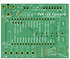
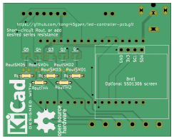
You can write your software using any framework you prefer. This board is built and will work out of the box for the kongr45gpen/ledstripesp32 project specifically.
This board is meant to function as a controller (generating low-power PWM signals from a network/wired input), as a dimmer (switching high-power LED lights on/off based on the input signal) or both.
The controller function is based on the ESP32-C6-DevKitC-1 development board, but other ESP32 development boards should be also usable (not tested).
The dimmer function relies on a few MOSFETs to control the current flow from the output.
The rest of the components are mostly optional and slightly improve the functionality of the board (connectors, pull-down resistors etc). The user can choose whichever components they need and assemble the board to their preference. Many components (e.g. DC barrel jack, headers, passives) may be replaceable with cheaper generic alternatives.
An all-around configuration should cost ~20€, and adding a screen, voltage regulator and detachable headers should move the price up to ~35€.
A total project cost for a simple RGB led control system could be: 5m 5050 12V RGB LED strip (10€) + 12V 1A power supply (10€) + PCB (6€) + components (20€) = 46€.
With example parts and prices from Mouser:
| Ref | Part | Qu. | CONT. | DIM. | Description | Price |
|---|---|---|---|---|---|---|
| Brd1 | 4-pin I2C SSD1306 | 1 | ❓ | Debugging info screen | 3€ | |
| C1 | C 100nF 0603 (1608 metric) | 1 | ✔️ | Decoupling capacitor | 0.1€ | |
| J1 | CUI PJ-063AH | 1 | ❓ | VIN Barrel connector | 1.5€ | |
| J2 | Molex SL 171971-0002 | 1 | ❓ | VIN Header connector | 0.8€ | |
| J3 | Molex SL 171971-0007 | 1 | ❓ | ❓ | PWM input/output connector (5 pins + GND) | 1.5€ |
| J4 | 5mm 6-pin screw terminal | 1 | ✔️ | Power output (5 pins + VDD) | 0.9€ | |
| J5 | Molex SL 171971-0003 | 1 | ❓ | Addressable LED output | 1.1€ | |
| LED1..5 | 0805 (2012 metric) LED | 5 | ❓ | ❓ | Indicator LEDs for PWM | 1.25€ |
| LED_POWER1 | 0805 (2012 metric) LED | 1 | ❓ | Indicator LED for VDD | 0.25€ | |
| Q1..5 | IRLTS6342 (N-MOSFET) | 5 | ✔️ | Control transistors (use as many as needed) | 1.7€ | |
| R1..6 | R 15kΩ 0603 (1608 metric) | 6 | ❓ | LED series resistors (use as many as needed) | 0.1€ | |
| Rpd1..5 | R 100kΩ 0603 (1608 metric) | 5 | ❓ | ❓ | Pull-down resistors to keep output off when disconnected | 0.1€ |
| SW1 | PTS647SM70SMTR2LFS | 1 | ❓ | ESP32 input switch | 0.2€ | |
| U1 | ESP32-C6-DevKitC-1 | 1 | ✔️ | ESP32 development kit | 8€ | |
| VR1 | Wurth 1769405241 | 1 | ❓ | Voltage regulator to provide 5V to ESP32 from VIN | 5€ |
| Part | Quantity | CONTROLLER | DIMMER | Description | Price |
|---|---|---|---|---|---|
| 4-pin header | 1 | ❓ | For screen (Brd1) | 0.7€ | |
| 16-pin-header | 2 | ❓ | For ESP32 (U1) | 5€ | |
| Molex 14-60-0024 | 1 | ❓ | Wire plug for J2 | 0.4€ | |
| Molex 14-60-0072 | 1 | ❓ | ❓ | Wire plug for J3 | 1.5€ |
| Molex 14-56-7032 | 1 | ❓ | Wire plug for J5 | 0.7€ |
Some solder bridges/solder jumpers may need to be soldered before any operation can take place.
| Ref | Pins | CONTROLLER | DIMMER | Description |
|---|---|---|---|---|
| JP1 | 3 | ✔️ | Controls the source of VDD for the LED power output. Bridge 2-1 to connect to 5V. Bridge 2-3 to connect to VIN (J1, J2). | |
| JP2 | 3 | ❓ | Controls the voltage source (typically 5V) for the addressable strip. Bridge 2-1 to connect to 5V. Bridge 2-3 to connect to VIN (J1, J2). | |
| JP3 | 2 | ✔️ | Bridge to connect power ground with digital ground. Must solder for proper operation. | |
| JP4 | 2 | ❓ | Bridge to connect VR1 output to 5V. Must solder to enable voltage regulation from VIN to ESP32 5V. Keep desoldered during debugging to prevent damaging your equipment. | |
| JPout1..5 | 2 | ✔️ | Bridge to connect transistor outputs to output connector. You can alternatively wire a series resistor here for your output, if needed. |
All-in-one controller, from Wi-Fi to RGB LED strip:
Addressable strip controller with debugging screen:
| Qty | Value | Footprint | References |
|---|---|---|---|
| 6 | 15k | Resistor_SMD:R_0603_1608Metric_Pad0.98x0.95mm_HandSolder | R1, R2, R3, R4, R5, R6 |
| 6 | LED | LED_SMD:LED_0805_2012Metric_Pad1.15x1.40mm_HandSolder | LED_POWER1, LED1, LED2, LED3, LED4, LED5 |
| 5 | 100k | Resistor_SMD:R_0603_1608Metric_Pad0.98x0.95mm_HandSolder | Rpd1, Rpd2, Rpd3, Rpd4, Rpd5 |
| 5 | IRLTS6342TRPBF | Package_SO:TSOP-6_1.65x3.05mm_P0.95mm | Q1, Q2, Q3, Q4, Q5 |
| 5 | SolderJumper_2_Open | Jumper:SolderJumper-2_P1.3mm_Open_TrianglePad1.0x1.5mm | JPout1, JPout2, JPout3, JPout4, JPout5 |
| 2 | SolderJumper_3_Bridged12 | Jumper:SolderJumper-3_P1.3mm_Open_RoundedPad1.0x1.5mm_NumberLabels | JP1, JP2 |
| 1 | 100n | Capacitor_SMD:C_0603_1608Metric_Pad1.08x0.95mm_HandSolder | C1 |
| 1 | Barrel_Jack_MountingPin | Connector_BarrelJack:BarrelJack_CUI_PJ-063AH_Horizontal_CircularHoles | J1 |
| 1 | Conn_01x02_Pin | Connector_Molex:Molex_SL_171971-0002_1x02_P2.54mm_Vertical | J2 |
| 1 | Conn_01x03_Pin | Connector_Molex:Molex_SL_171971-0003_1x03_P2.54mm_Vertical | J5 |
| 1 | Conn_01x07_Pin | Connector_Molex:Molex_SL_171971-0007_1x07_P2.54mm_Vertical | J3 |
| 1 | ESP32-C6-DevKitC-1 | Espressif:ESP32-C6-DevKitC-1 | U1 |
| 1 | SSD1306 | SSD1306:128x64OLED | Brd1 |
| 1 | SW_Push | controller_library:SWITCH-4 | SW1 |
| 1 | Screw_Terminal_01x06 | TerminalBlock_RND:TerminalBlock_RND_205-00005_1x06_P5.00mm_Horizontal | J4 |
| 1 | SolderJumper_2_Bridged | Jumper:SolderJumper-2_P1.3mm_Open_RoundedPad1.0x1.5mm | JP3 |
| 1 | SolderJumper_2_Open | Jumper:SolderJumper-2_P1.3mm_Open_RoundedPad1.0x1.5mm | JP4 |
| 1 | Wurth Elektronik 1769405x41 | controller_library:1769405x41 | VR1 |
The 41 most common of 44 parts.

cvonk/OPNpool
Integrates the functionality of a Pentair pool controller into the smart home using ESP32 SoC.

embedded-purdue/IntelliThings
From IoT to AIoT: ESP32-C6 sensor nodes, Home Assistant and an LLM agent that acts through MCP

Angelpele/F1-Steering-Wheel
F1 Functional Steering Wheel based on the ESP32

leehambley/leels
Lee LS (Lead Screw). Forked and simplified from kachurovskiy/nanoels, rewritten in Rust and simplified for a true ELS implementation not a quasi-CNC controller

Poent/RC-Snowblower
Working on designing the impeller and auger portion of the snowblower. Switched from using a worm gear assembly to a custom ring and pinion setup using a spiral bevel gear.


Ekam-wadhwa1/nexus.terminal
it is a portable touchscreen device with 2 displays powered by a lattepanda iota with 16gb ram and intel n150. paired with a custom built mechanical keyboard for typing,coding,streaming and web browsing
It measures 62.5 × 50.2 mm and has 2 copper layers, 1.6 mm thick.
44 parts, built around the ESP32-C6-DEVKITC-1-N8 and IRLTS6342TRPBF. The full list of its parts is on this page, with links to each part's symbol and footprint where PCBKit's library has them.
From the kongr45gpen/led-controller-pcb repository on GitHub, at the commit this page was made from: the board is controller.kicad_pcb and its schematic controller.kicad_sch. PCBKit opens the board in the browser, with nothing to install.
Its repository publishes it under the CERN-OHL-W-2.0 licence: you may reuse it on that licence's terms (keep the author's notice, and for a copyleft licence share your changes alike).