
2 layers220 × 300 mm
Transit
thebenedict/seattletransit-hardware
Schematic and PCB for a circuit board map of Seattle area public transit.
448 parts14CERN-OHL-W-2.0

 KolijnWolfaardt/TTN_sensor_node
An experimental sensor node for The Things Network.
Lora sensor is an open-source printed circuit board by KolijnWolfaardt, from the KolijnWolfaardt/TTN_sensor_node repository on GitHub. It is a 2-layer board of 48.3 × 48.3 mm with 82 parts on 53 nets, routed with 850 tracks and 75 vias.
It is built around the BH1603FVC-TR. Its parts include 26 resistors, 17 capacitors, 10 connectors, 6 ICs and 3 transistors. It belongs with the sensors and measurement and radio and wireless boards and the PIC boards of this library.
This is a basic sensor board I designed to experiment with the LORAWAN protocol, and The Things Network infrastructure. It is by no means intended to be a good or complete example of all the capabilities of either.
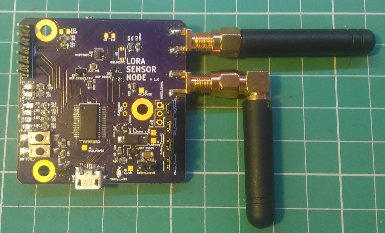
The board uses a Microchip RN2483 to perform the RF communication and a PIC18F46J50 for the other work. The sensors were chosen based on what was available, for experimentation. Other sensors can easily be used.
The board is powered by a single LiPo battery, which is regulated down to 3.3v. To charge the LiPo battery, A MCP73831/2 Battery Management IC is used. The power part is not finished yet, as the batteries have not arrived, so there might be updates here.
Thanks to https://github.com/jpmeijers/RN2483shield for the RN2483 component and module.
The schematic and PCB layout were created using KiCad, and can be found in the PCB Layout folder. The gerber files and schematic PDF can also be found there.
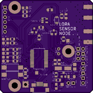
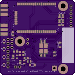
The firmware can be found in the Firmware folder, and is intended for the XC8 compiler using the MPLABX IDE. The board is programmed with a PicKIT 3 programmer, but the PicKIT 2 should also work. The basic flow of the program is shown in basic_control_flow.dia (Open with http://dia-installer.de/ flowchart editor) inside the Firmware folder.
comment [blocked]: # (For more details on the software, see Firmware/README.md )
The radio connects via ABP (Activation by personalization). The keys were programmed beforehand using a USB-serial converter, and the radio stores them internally. I will add some code later to set them in the code.
USB stack adapted from https://github.com/signal11/m-stack.git, for its license see the LICENSE file.
There are two mistakes on the board:
These are suggestions that require more rework, but are only for ease of use.
| Qty | Value | Footprint | References |
|---|---|---|---|
| 8 | 0 | Resistors_SMD:R_0805 | R1, R2, R5, R6, R8, R11, R12, R13 |
| 8 | 100nF | Capacitors_SMD:C_0805 | C1, C2, C6, C7, C8, C15, C16, C17 |
| 7 | 330 | Resistors_SMD:R_0805 | R3, R4, R15, R18, R19, R20, R21 |
| 7 | LED | LEDs:LED_0805 | Charge_LED1, LED0, LED1, LED2, LED3, RF_LED_0, RF_LED_1 |
| 5 | 10k | Resistors_SMD:R_0805 | R9, R16, R17, R22, R23 |
| 5 | CONN_01X02 | Pin_Headers:Pin_Header_Straight_1x02_Pitch2.54mm | Battery_Current1, Battery_Input1, Charge_Current1, MCU_Current1, RF_Current1 |
| 3 | 1uF | Capacitors_SMD:C_0805 | C3, C9, C14 |
| 3 | CONN_01X01 | Mounting_Holes:MountingHole_3.2mm_M3_Pad | J1, J2, J3 |
| 2 | 22pF | Capacitors_SMD:C_0805 | C10, C11 |
| 2 | 4.7uF | Capacitors_SMD:C_1206 | C4, C5 |
| 2 | 47k | Resistors_SMD:R_0805 | R24, R25 |
| 2 | CONN_01X02 | libraries:SMA_edge_connect | RF_HIGH_1, RF_LOW_1 |
| 2 | NXP BSS84 | TO_SOT_Packages_SMD:SOT-23 | Q1, Q3 |
| 2 | SwitchTactile | Buttons_Switches_SMD:SW_SPST_REED_CT05-XXXX-G1 | BUTTON_1, BUTTON_2 |
| 1 | 10nF | Capacitors_SMD:C_0805 | C12 |
| 1 | 10uF | Capacitors_SMD:C_1206 | C13 |
| 1 | 2k | Resistors_SMD:R_0805 | R10 |
| 1 | 3.3V | Measurement_Points:Measurement_Point_Square-SMD-Pad_Small | J5 |
| 1 | 470 | Resistors_SMD:R_0805 | R7 |
| 1 | 4k7 | Resistors_SMD:R_0805 | R14 |
| 1 | BH1603FVC | libraries:BH1603FVC | U5 |
| 1 | CONN_01X03 | Pin_Headers:Pin_Header_Straight_1x03_Pitch2.54mm | UART2_CONN1 |
| 1 | CONN_01X06 | Pin_Headers:Pin_Header_Straight_1x06_Pitch2.54mm | PICKIT1 |
| 1 | D_Zener | Diodes_SMD:D_SMA_Handsoldering | D1 |
| 1 | FA_238 | libraries:Crystal_FA-238 | Y1 |
| 1 | GND | Measurement_Points:Measurement_Point_Square-TH_Big | J9 |
| 1 | MCP73831/2 | TO_SOT_Packages_SMD:TSOT-23-5 | U2 |
| 1 | MCP9700T-E | TO_SOT_Packages_SMD:SOT-23-5 | U6 |
| 1 | MCU_POWER | Measurement_Points:Measurement_Point_Square-SMD-Pad_Small | J6 |
| 1 | NXP 2N7002,215 | TO_SOT_Packages_SMD:SOT-23 | Q2 |
| 1 | PIC18F2XJ50 | Housings_SSOP:SSOP-28_5.3x10.2mm_Pitch0.65mm | U4 |
| 1 | RF_POWER | Measurement_Points:Measurement_Point_Square-SMD-Pad_Small | J7 |
| 1 | RN2483 | libraries:RN2483 | U1 |
| 1 | R_Variable | Resistors_ThroughHole:R_Axial_DIN0204_L3.6mm_D1.6mm_P2.54mm_Vertical | R26 |
| 1 | TPS736 | TO_SOT_Packages_SMD:SOT-23-5 | U3 |
| 1 | USB_A | libraries:USB_Micro | P1 |
| 1 | V_Battery | Measurement_Points:Measurement_Point_Square-SMD-Pad_Small | J4 |
| 1 | V_USB | Measurement_Points:Measurement_Point_Square-SMD-Pad_Small | J8 |
It measures 48.3 × 48.3 mm and has 2 copper layers, 1.6 mm thick.
82 parts, built around the BH1603FVC-TR. The full list of its parts is on this page, with links to each part's symbol and footprint where PCBKit's library has them.
From the KolijnWolfaardt/TTN_sensor_node repository on GitHub, at the commit this page was made from: the board is PCB Layout/lora_sensor.kicad_pcb. PCBKit opens the board in the browser, with nothing to install.
Its repository states no licence, so its author keeps all rights: ask KolijnWolfaardt before reusing the design.
thebenedict/seattletransit-hardware
Schematic and PCB for a circuit board map of Seattle area public transit.


baldengineer/bit-preserve
Project for capturing vintage, classic, aka old computer schematics in KiCad.


CRImier/MyKiCad
My KiCad boards. Can't be bothered uploading individually anymore, so here you go.

nodestark/mdb-esp32-cashless
ESP32-based MDB cashless device for vending machines, supporting EVA DTS DEX/DDCMP telemetry and payments over the MDB protocol via Bluetooth and MQTT

krikzz/open-ed
Open-ED is a very simple and cheap open source Genesis/Megadrive cartridge. The cartridge does not have its own processor or FPGA, it is built in the old school style using only memory and discrete logic.
