2 layers50.7 × 48.4 mm
Star
klushok-etv/christmas2021
For the list of To-Do's check the TODO list, feel free to add any issues or tasks as well!
36 parts

 klushok-etv/christmas2021
For the list of To-Do's check the TODO list, feel free to add any issues or tasks as well!
Programmer is an open-source printed circuit board by klushok-etv, from the klushok-etv/christmas2021 repository on GitHub. It is a 2-layer board of 50 × 50 mm with 28 parts on 29 nets, routed with 140 tracks and 62 vias.
It is built around the CH340G, AMS1117-3.3 and MMBT3904. Its parts include 6 capacitors, 6 resistors, 3 connectors, 2 ICs and 2 transistors. It belongs with the interfaces and adapters boards of this library.


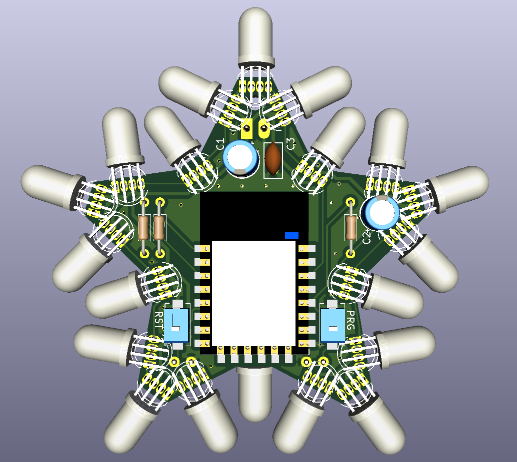
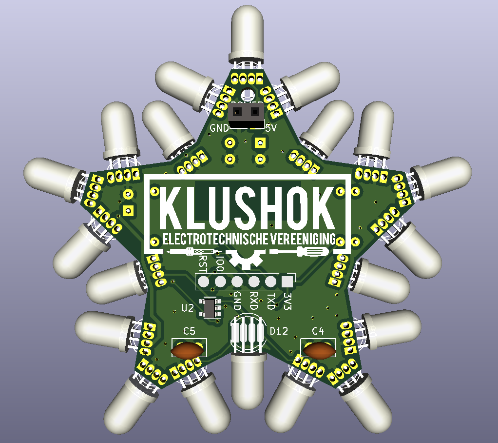
The PCB outline can be generated from the included svg file star template using the svg2shenzen plugin.
For the list of To-Do's check the TODO list, feel free to add any issues or tasks as well!
ESP12F has 15 (17 including rx tx) gpio available. There are 45 signals required to controll each color individually. By combining the same color every 5 leds, all leds can be controlled. Issue that remains is the current requirement per GPIO which far exceeds the limit of the pin. The current can be increased by adding transistors/fets or something like 2 of the ULN2803 and common anode leds.
ESP kicad lib: https://github.com/jdunmire/kicad-ESP8266. -> this library has most models but the centers of the pads are located in an odd place. the symbol is also not colored.
This design makes use of the APA106 leds which are pincompatible with the pl9823 when pin 1 is attached to pin 4 etc. Both of these led types can be controlled as if they were a WS2812.
The two buttons are reset and io0, required for programming. IO0 can also be used as a user input pin.
THT components have been chosen where possible to easy soldering by hand. Components with a SMD package are still solderable by hand, using a tweezer is advised.
Power is fed through to the connectors at the top of the pcb, a jst or other connector can be soldered in place to ensure polarity is correct. No reverse polarity protection is in place!
The star can be programmed using the pads on the back. Wires can be soldered to the pads or pogo pins could be used.
The committee might make a custom programmer to ease flashing for the first time after which OTA/wifimanager can be uploaded. An anternative idea for the firmware might be WLED.
| Qty | Value | Footprint | References |
|---|---|---|---|
| 2 | 10k | Resistor_SMD:R_0805_2012Metric | R3, R4 |
| 2 | 10uF | Capacitor_SMD:C_0805_2012Metric | C1, C3 |
| 2 | 22pF | Capacitor_SMD:C_0805_2012Metric | C5, C6 |
| 2 | 5k1 | Resistor_SMD:R_0805_2012Metric | R5, R6 |
| 2 | MMBT3904 | Package_TO_SOT_SMD:SOT-23 | Q1, Q2 |
| 1 | 100nF | Capacitor_SMD:C_0805_2012Metric | C4 |
| 1 | 10uF | Capacitor_Tantalum_SMD:CP_EIA-3216-10_Kemet-I | C2 |
| 1 | 12MHz | Crystal:Crystal_HC49-U_Vertical | Y1 |
| 1 | 300 | Resistor_SMD:R_0805_2012Metric | R1 |
| 1 | 470 | Resistor_SMD:R_0805_2012Metric | R2 |
| 1 | AMS1117-3.3 | Package_TO_SOT_SMD:SOT-223-3_TabPin2 | U1 |
| 1 | CH340G | Package_SO:SOIC-16_3.9x9.9mm_P1.27mm | U2 |
| 1 | PWR | LED_SMD:LED_1206_3216Metric | D1 |
| 1 | Pogo pins | programmer:pogo_conn_01x07_oval | J2 |
| 1 | USB_C_Receptacle_USB2.0 | Connector_USB:USB_C_Receptacle_HRO_TYPE-C-31-M-12 | J1 |
| 1 | Val** | programmer:progpin_position_7pin | Ref** |
| 1 | power select | Connector_PinSocket_2.54mm:PinSocket_1x04_P2.54mm_Vertical | J3 |
The 22 most common of 28 parts.
klushok-etv/christmas2021
For the list of To-Do's check the TODO list, feel free to add any issues or tasks as well!


SteveLRojas/MC-10_Tape_Emulator
Unified HW and SW repository for the TRS-80 MC-10 tape emulator project.


NVIDIA-AI-IOT/my-jetson-nano-baseboard
An open source Jetson Nano baseboard and tools to design your own.

GadgetReboot/ESP32-A1S
Breakout PCB for the ESP32-A1S module including an audio amp and basic GPIO headers, USB interface

garrettsworkshop/WarpSE
WIP 25 MHz MC68HC000-based accelerator card for Macintosh SE

austinscreations/Oxrs-Black
a custom rack controller that is based of the rack32 but includes some upgrades and major changes
It measures 50 × 50 mm and has 2 copper layers, 1.6 mm thick.
28 parts, built around the CH340G, AMS1117-3.3 and MMBT3904. The full list of its parts is on this page, with links to each part's symbol and footprint where PCBKit's library has them.
From the klushok-etv/christmas2021 repository on GitHub, at the commit this page was made from: the board is pcb/programmer/programmer.kicad_pcb. PCBKit opens the board in the browser, with nothing to install.
Its repository states no licence, so its author keeps all rights: ask klushok-etv before reusing the design.