
2 layers15.3 × 19.3 mm
Kicad hx711 tyny85
IvDm/Z-probe-on-smd-resistors-2512
Auto bed level strain gage for 3D printer using resistors 2512 instead of strain gauges.
18 parts150GPL-3.0
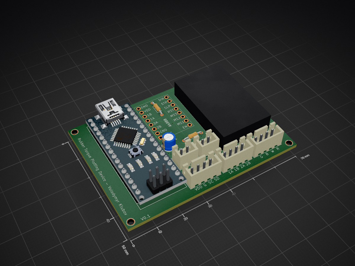
 klubov/torque-plotting-device
Device for measuring torque vs. turns in rubber bands
Torque Measurement Meter is an open-source printed circuit board by klubov, from the klubov/torque-plotting-device repository on GitHub, published under the MIT licence. It is a 2-layer board of 70 × 50 mm with 13 parts on 47 nets, routed with 161 tracks and 9 vias.
It is built around the HX711. It belongs with the sensors and measurement boards of this library.
This device is designed to plot the relationship between torque and the number of turns in a rubber band. It has been tested using a rubber motor intended for an F1M class model aircraft and can also be used with rubber bands for F1D class models. With some additional adjustments, the device can support experiments on rubber bands of other sizes for educational or research purposes.
The main mechanical components of the device are produced using 3D printing. All necessary parts can be found on Thingiverse, as well as in this repository.
The following components were used to build the electronic circuit of the device:
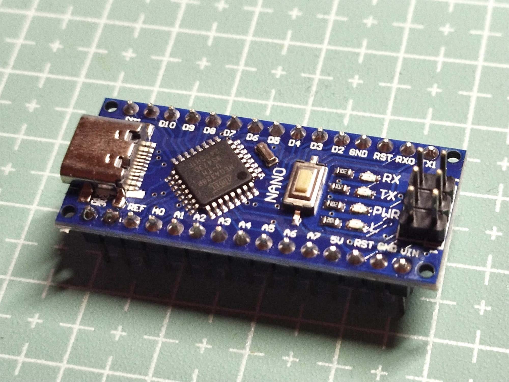
Controller Nano Atmega 328P
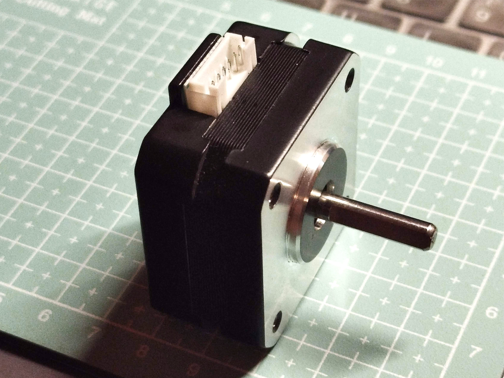
Stepper motor NEMA 17 17HS4023
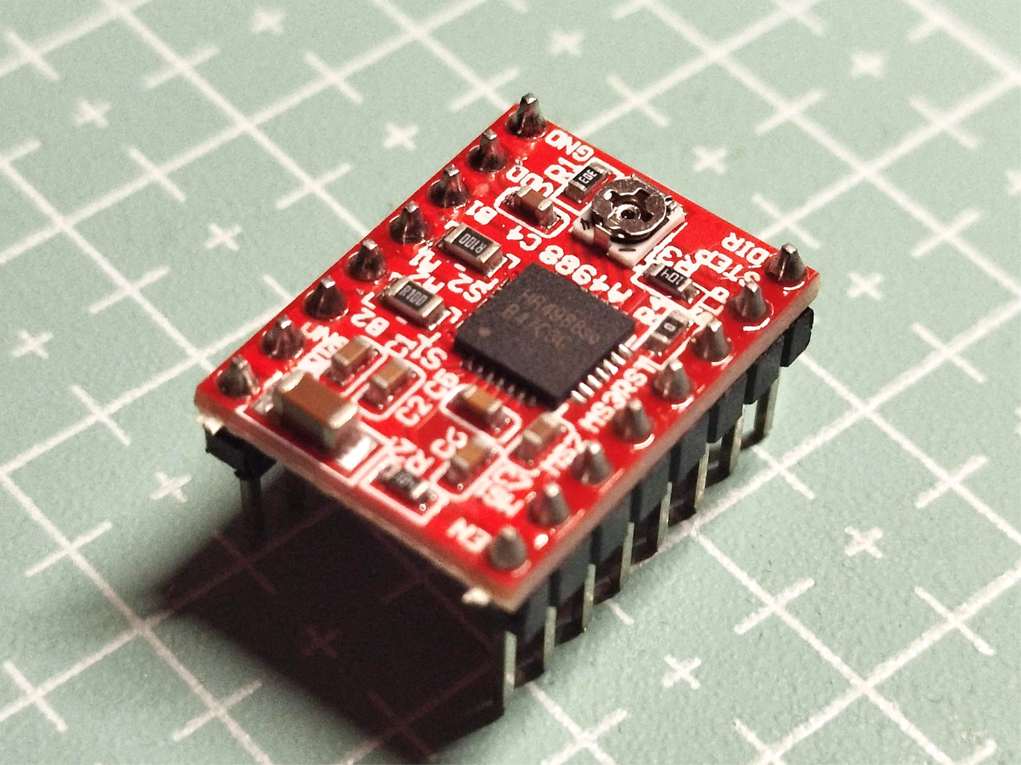
A4988 Stepper Motor Driver
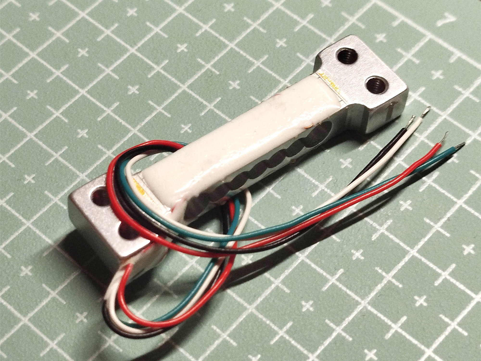
100 g Load Cell
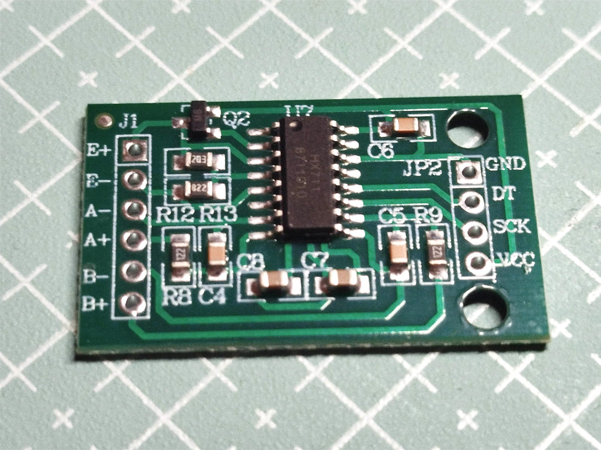
HX711 Amplifier board
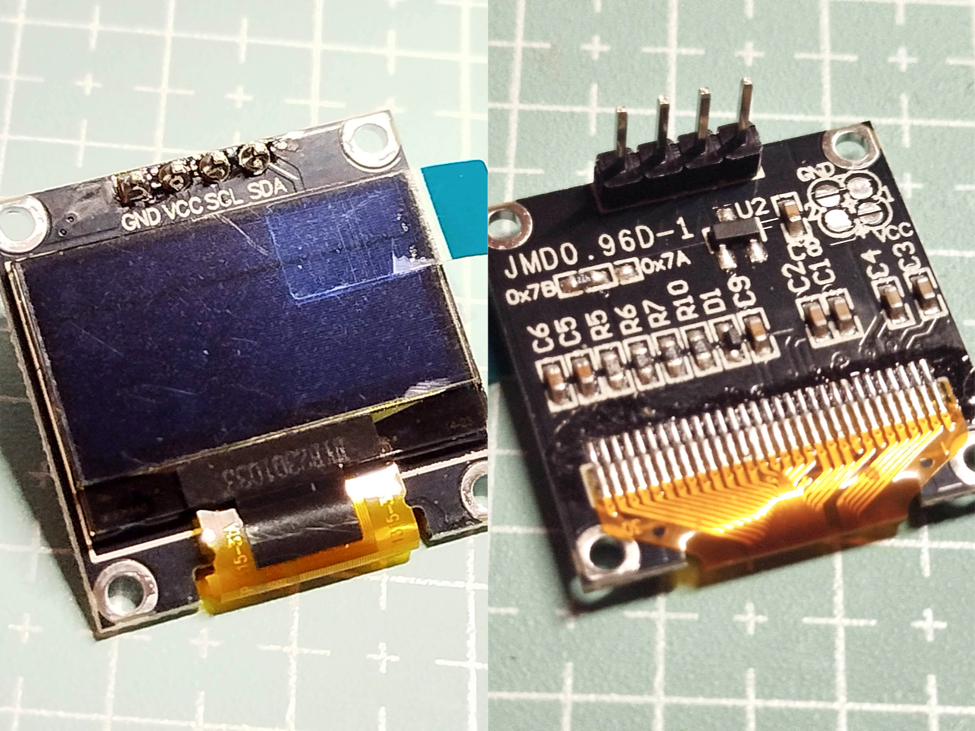
0.96" OLED Display Screen Module 128x64
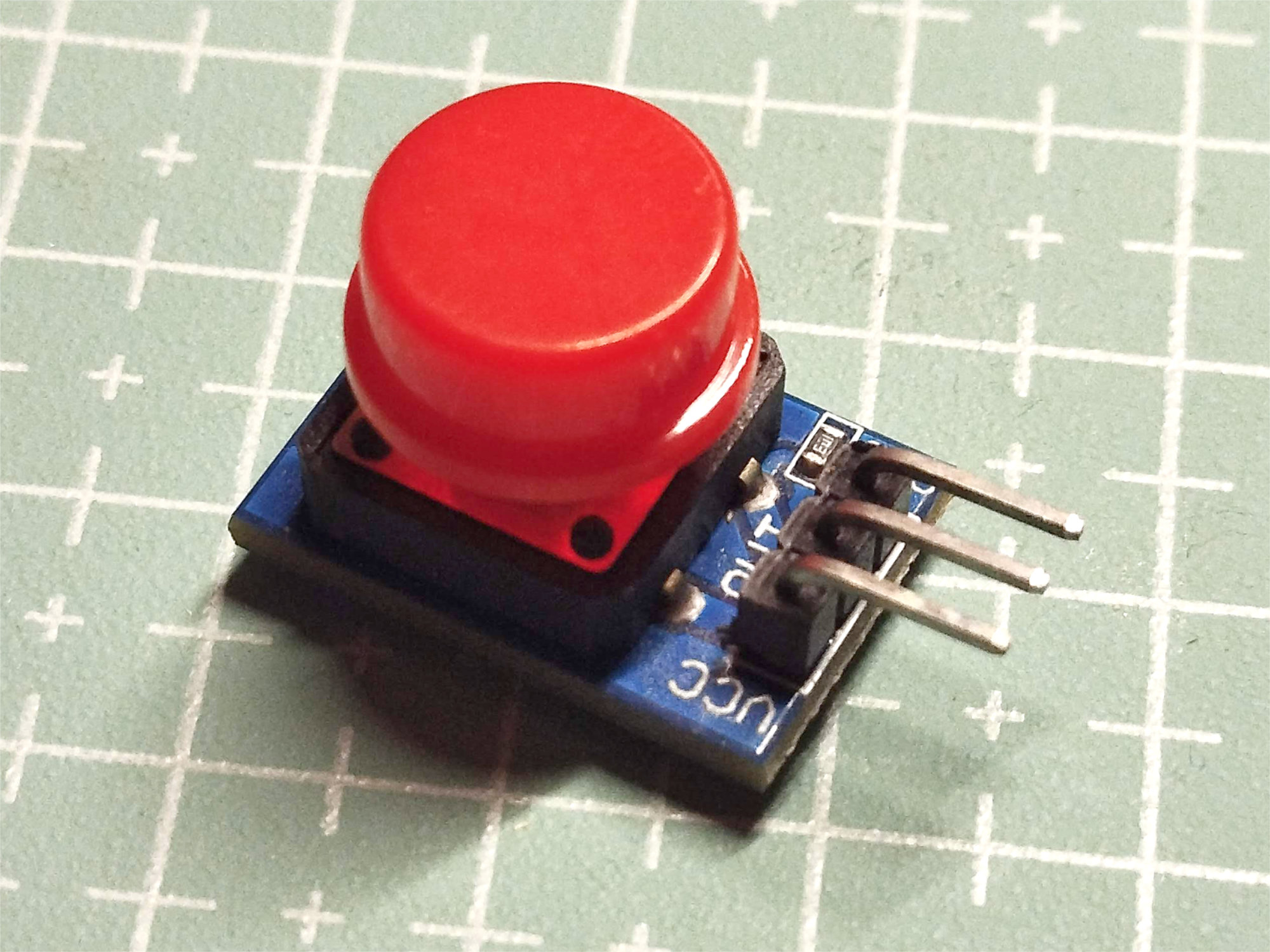
12 mm Button module
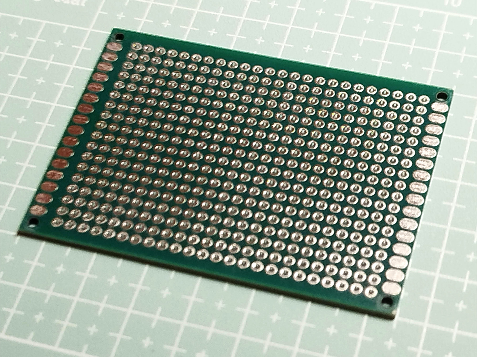
70x50 Prototype Circuit Board
Several photos of the assembled circuit board:


The file torque.ino contains the program used to operate the device. For the sake of brevity, the process of obtaining the calibration factor for the load cell has been omitted (the value used in the code is -7492.035156).
The pcb folder contains the device’s printed circuit board files — thanks to Rick Diaz. It includes both the original KiCad files and the Gerber files. There is also an archive of Gerber files ready to be sent to a PCB manufacturer.
| Qty | Value | Footprint | References |
|---|---|---|---|
| 3 | 1K | Resistor_THT:R_Axial_DIN0204_L3.6mm_D1.6mm_P7.62mm_Horizontal | 1K, 1K, 1K |
| 2 | ~ | Connector_JST:JST_XH_B4B-XH-A_1x04_P2.50mm_Vertical | Load Cell, OLED |
| 1 | A4988_Driver | My_Library:A4988 Stepper Driver | A4988 |
| 1 | Arduino Nano | My_Library:Arduino_Nano_v3 | Arduino Nano |
| 1 | C_Small_US | Capacitor_THT:CP_Radial_D5.0mm_P2.50mm | C1 |
| 1 | HX711 | My_Library:HX711 Load Cell Adapter | HX711 |
| 1 | Jack-DC | Connector_JST:JST_XH_B2B-XH-A_1x02_P2.50mm_Vertical | Mot Pwr |
| 1 | Motor | Connector_JST:JST_XH_B4B-XH-A_1x04_P2.50mm_Vertical | Motor |
| 1 | Switch | Connector_JST:JST_XH_B2B-XH-A_1x02_P2.50mm_Vertical | Switch |
The 12 most common of 13 parts.
It measures 70 × 50 mm and has 2 copper layers, 1.6 mm thick.
13 parts, built around the HX711. The full list of its parts is on this page, with links to each part's symbol and footprint where PCBKit's library has them.
From the klubov/torque-plotting-device repository on GitHub, at the commit this page was made from: the board is pcb/KiCad/Torque_Measurement_Meter.kicad_pcb and its schematic pcb/KiCad/Torque_Measurement_Meter.kicad_sch. PCBKit opens the board in the browser, with nothing to install.
Its repository publishes it under the MIT licence: you may reuse it on that licence's terms (keep the author's notice, and for a copyleft licence share your changes alike).
IvDm/Z-probe-on-smd-resistors-2512
Auto bed level strain gage for 3D printer using resistors 2512 instead of strain gauges.


szbeni/forcegauge
Traning for climbing. Load cell with HX711 and real time plotting,

MartinVerges/womolin-waterlevel
DIY project to build a smart fuel sensor for RVs or in other projects. It is based on air pressure and is able to measure fresh water as well as grey and black water levels with high precision.


ikonis/OpenWatts
OpenWatts is a crank-mounted, single-sided cycling power meter built around an ESP32-C3. A bonded strain-gauge bridge and HX711 measure crank torque, while an LSM6DS3 IMU provides cadence and motion wake.