4 layers60 × 36 mm
Camera Project
Raphi25/Camera-Project
This project investigates the development of a low-cost wearable camera system intended to support caregivers by capturing images throughout the wearer's daily life.
132 parts
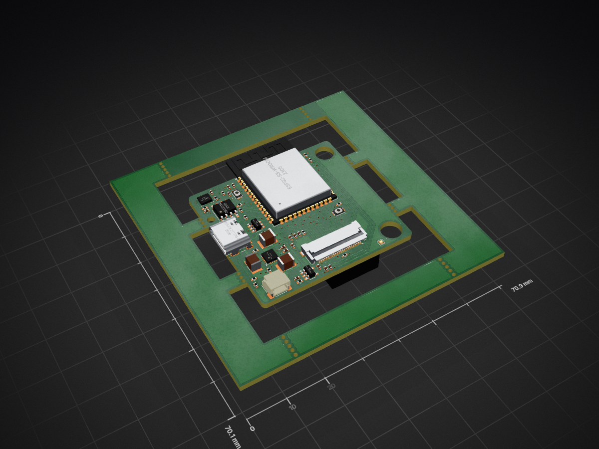
 kitnol/Camera_project
(See the README.md file in the upper level 'examples' directory for more information about examples.)
Wear Camera is an open-source printed circuit board by kitnol, from the kitnol/Camera_project repository on GitHub. It is a 4-layer board of 70.9 × 70.1 mm with 75 parts on 82 nets, routed with 622 tracks and 113 vias.
It is built around the ESP32-S3-WROOM-1-N8, AP2111H-3.3TRG1 and BQ24074RGTR, with the DS3231MZ/V+, LP5907MFX-1.5 and LSM6DSM among its other parts. Its parts include 32 resistors, 20 capacitors, 9 ICs, 3 diodes and 3 connectors. It belongs with the ESP32 boards of this library.


| Supported Targets | ESP32-S3 |
|---|
esp_console_repl)(See the README.md file in the upper level 'examples' directory for more information about examples.)
This example illustrates the usage of the REPL (Read-Eval-Print Loop) APIs of the Console Component to create an interactive shell on the ESP chip. The interactive shell running on the ESP chip can then be controlled/interacted with over a serial interface. This example supports UART and USB interfaces.
The interactive shell implemented in this example contains a wide variety of commands, and can act as a basis for applications that require a command-line interface (CLI).
Compared to the advanced console example, this example requires less code to initialize and run the console. esp_console_repl API handles most of the details. If you'd like to customize the way console works (for example, process console commands in an existing task), please check the advanced console example.
This example can be used on boards with UART and USB interfaces. The sections below explain how to set up the board and configure the example.
When UART interface is used, this example should run on any commonly available Espressif development board. UART interface is enabled by default (CONFIG_ESP_CONSOLE_UART_DEFAULT option in menuconfig). No extra configuration is required.
NOTE: We recommend to disable the secondary console output on chips with USB_SERIAL_JTAG since the secondary serial is output-only and would not be very useful when using a console application. This is why the secondary console output is deactivated per default (CONFIG_ESP_CONSOLE_SECONDARY_NONE=y)
On chips with USB_SERIAL_JTAG peripheral, console example can be used over the USB serial port.
idf.py menuconfig and enable CONFIG_ESP_CONSOLE_USB_SERIAL_JTAG option.For more details about connecting and configuring USB_SERIAL_JTAG (including pin numbers), see the IDF Programming Guide:
USB_OTG peripheral can also provide a USB serial port which works with this example.
idf.py menuconfig and enable CONFIG_ESP_CONSOLE_USB_CDC option.For more details about connecting and configuring USB_OTG (including pin numbers), see the IDF Programming Guide:
This example has an option to store the command history in Flash. This option is enabled by default.
To disable this, run idf.py menuconfig and disable CONFIG_CONSOLE_STORE_HISTORY option.
Build the project and flash it to the board, then run monitor tool to view serial output:
idf.py -p PORT flash monitor(Replace PORT with the name of the serial port to use.)
(To exit the serial monitor, type Ctrl-].)
See the Getting Started Guide for full steps to configure and use ESP-IDF to build projects.
Enter the help command get a full list of all available commands. The following is a sample session of the Console Example where a variety of commands provided by the Console Example are used.
On ESP32, GPIO15 may be connected to GND to remove the boot log output.
This is an example of ESP-IDF console component.
Type 'help' to get the list of commands.
Use UP/DOWN arrows to navigate through command history.
Press TAB when typing command name to auto-complete.
[esp32]> help
help
  Print the list of registered commands

free
  Get the total size of heap memory available

restart
  Restart the program

deep_sleep  [-t <t>] [--io=<n>] [--io_level=<0|1>]
  Enter deep sleep mode. Two wakeup modes are supported: timer and GPIO. If no
  wakeup option is specified, will sleep indefinitely.
  -t, --time=<t>  Wake up time, ms
      --io=<n>  If specified, wakeup using GPIO with given number
  --io_level=<0|1>  GPIO level to trigger wakeup

join  [--timeout=<t>] <ssid> [<pass>]
  Join WiFi AP as a station
--timeout=<t> Connection timeout, msThe line endings in the Console Example are configured to match particular serial monitors. Therefore, if the following log output appears, consider using a different serial monitor (e.g. Putty for Windows) or modify the example's UART configuration.
This is an example of ESP-IDF console component.
Type 'help' to get the list of commands.
Use UP/DOWN arrows to navigate through command history.
Press TAB when typing command name to auto-complete.
Your terminal application does not support escape sequences.
Line editing and history features are disabled.
On Windows, try using Putty instead.
esp32>| Qty | Value | Footprint | References |
|---|---|---|---|
| 14 | 10k | Resistor_SMD:R_0402_1005Metric | R1, R2, R3, R4, R5, R6, R7, R11, R18, R19, R21, R29, R31, R32 |
| 6 | 100n | Capacitor_SMD:C_0402_1005Metric | C1, C5, C6, C12, C13, C14 |
| 6 | 1u | Capacitor_SMD:C_0402_1005Metric | C3, C9, C10, C11, C15, C22 |
| 5 | 3.3k | Resistor_SMD:R_0402_1005Metric | R8, R9, R10, R14, R30 |
| 4 | 4.7u | Capacitor_SMD:C_0402_1005Metric | C4, C7, C8, C23 |
| 3 | 100k | Resistor_SMD:R_0402_1005Metric | R16, R17, R23 |
| 3 | 10u | Capacitor_SMD:C_1210_3225Metric_Pad1.33x2.70mm_HandSolder | C26, C27, C28 |
| 3 | 150R | Resistor_SMD:R_0402_1005Metric | R12, R13, R15 |
| 2 | 16-213/BHC-AN1P2/3T | Diode_SMD:D_0402_1005Metric | D2, D15 |
| 2 | 5.1k | Resistor_SMD:R_0805_2012Metric_Pad1.20x1.40mm_HandSolder | R24, R25 |
| 2 | C913778 | WearCam_Components_Lib:SW_EVPBB4A9B000 | S1, S2 |
| 2 | SolderJumper_2_Open | Jumper:SolderJumper-2_P1.3mm_Open_RoundedPad1.0x1.5mm | JP1, JP2 |
| 2 | TestPoint_Small | TestPoint:TestPoint_Pad_1.0x1.0mm | TP1, TP2 |
| 1 | 1.62k | Resistor_SMD:R_0402_1005Metric | R27 |
| 1 | 10u | Capacitor_SMD:C_0402_1005Metric | C2 |
| 1 | 16-213SURC/S530-A4/TR8 | Diode_SMD:D_0402_1005Metric | D16 |
| 1 | 20k | Resistor_SMD:R_0402_1005Metric | R20 |
| 1 | 24.9k | Resistor_SMD:R_0402_1005Metric | R22 |
| 1 | 49.9k | Resistor_SMD:R_0402_1005Metric | R28 |
| 1 | 750 | Resistor_SMD:R_0402_1005Metric | R26 |
| 1 | AP2111H-3.3TRG1 | Package_TO_SOT_SMD:SOT-223 | U1 |
| 1 | BQ24074RGT | Package_DFN_QFN:VQFN-16-1EP_3x3mm_P0.5mm_EP1.6x1.6mm | U11 |
| 1 | C238097 | WearCam_Components_Lib:BAT_3000 | BT1 |
| 1 | Conn_01x03_Pin | Connector_JST:JST_SH_SM03B-SRSS-TB_1x03-1MP_P1.00mm_Horizontal | J4 |
| 1 | DS3231MZ | Package_SO:SOIC-8_3.9x4.9mm_P1.27mm | U3 |
| 1 | ESP32-S3-WROOM-1 | RF_Module:ESP32-S3-WROOM-1 | U2 |
| 1 | LP5907MFX-1.5 | Package_TO_SOT_SMD:SOT-23-5 | U5 |
| 1 | LSM6DSM | Package_LGA:LGA-14_3x2.5mm_P0.5mm_LayoutBorder3x4y | U4 |
| 1 | Molex 217179-0001 | ARC_Components_Lib:MOLEX_2171790001 | U9 |
| 1 | Molex 5033981892 | ARC_Components_Lib:CONN_503398-1892_MOL | J3 |
| 1 | SolderJumper_3_Bridged12 | Jumper:SolderJumper-3_P1.3mm_Bridged2Bar12_RoundedPad1.0x1.5mm | JP5 |
| 1 | TLV74328PDBVR | Package_TO_SOT_SMD:SOT-23-5 | U6 |
| 1 | USBLC6-2SC6 | Package_TO_SOT_SMD:SOT-23-6 | U10 |
| 1 | XF2M-2415-1A BY OMZ | WearCam_Components_Lib:OMRON_XF2M-2415-1A | J2 |
It measures 70.9 × 70.1 mm and has 4 copper layers, 1.6 mm thick.
75 parts, built around the ESP32-S3-WROOM-1-N8, AP2111H-3.3TRG1, BQ24074RGTR and DS3231MZ/V+. The full list of its parts is on this page, with links to each part's symbol and footprint where PCBKit's library has them.
From the kitnol/Camera_project repository on GitHub, at the commit this page was made from: the board is PCB/Wear Camera/Wear Camera.kicad_pcb and its schematic PCB/Wear Camera/Wear Camera.kicad_sch. PCBKit opens the board in the browser, with nothing to install.
Its repository states no licence, so its author keeps all rights: ask kitnol before reusing the design.
Raphi25/Camera-Project
This project investigates the development of a low-cost wearable camera system intended to support caregivers by capturing images throughout the wearer's daily life.

PyroVision-ThermalCam/Mainboard
Mainboard for the PyroVision thermal camera.


Chicken-Fried/STM32-NanoCortex
Ultra-compact USB-C development board powered by STM32F042 (ARM Cortex-M0) with native DFU, ceramic-only LDO power stage & CaveRover branding.


lunakiller/project_tamiya
Custom open-source RC car system based on STM32 MCUs
