

4 layers100 × 100 mm

 kinoshita-lab/StemsMIDI5
MIDI Controller for Traktor Stems
StemsMIDI is an open-source printed circuit board by kinoshita-lab, from the kinoshita-lab/StemsMIDI repository on GitHub, published under the MIT licence. It is a 2-layer board of 105 × 195 mm with 191 parts on 117 nets, routed with 2,985 tracks and 913 vias.
It is built around the 74HC165D and 74HC4051. Its parts include 55 capacitors, 49 resistors, 24 diodes, 24 switches and 7 ICs.
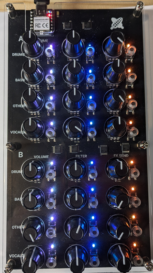
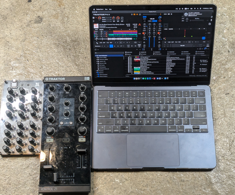
releases (https://github.com/kinoshita-lab/StemsMIDI/releases)
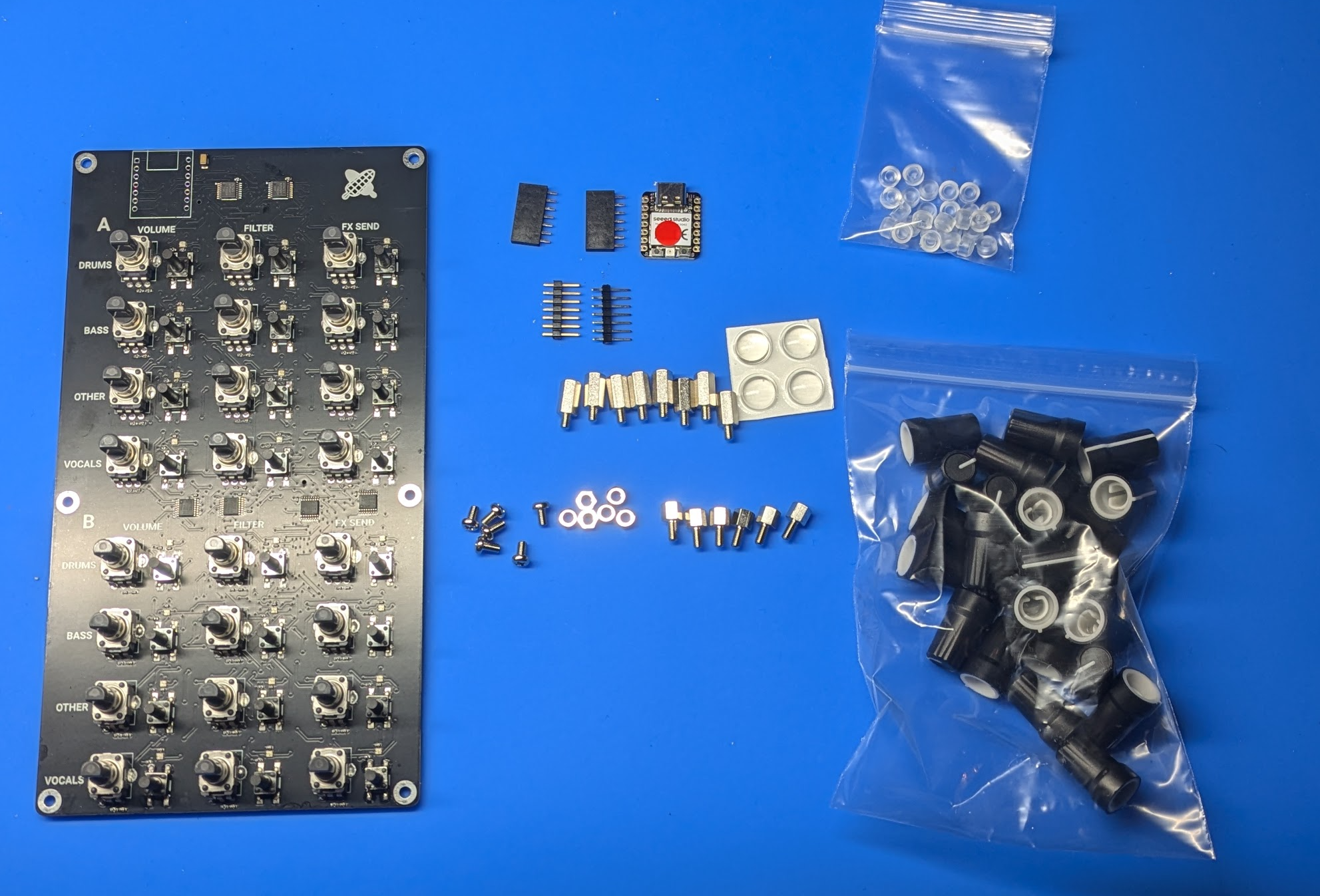
Recommend following procedure to align pins. tips: You can solder MCU Module directly on the PCBA board.
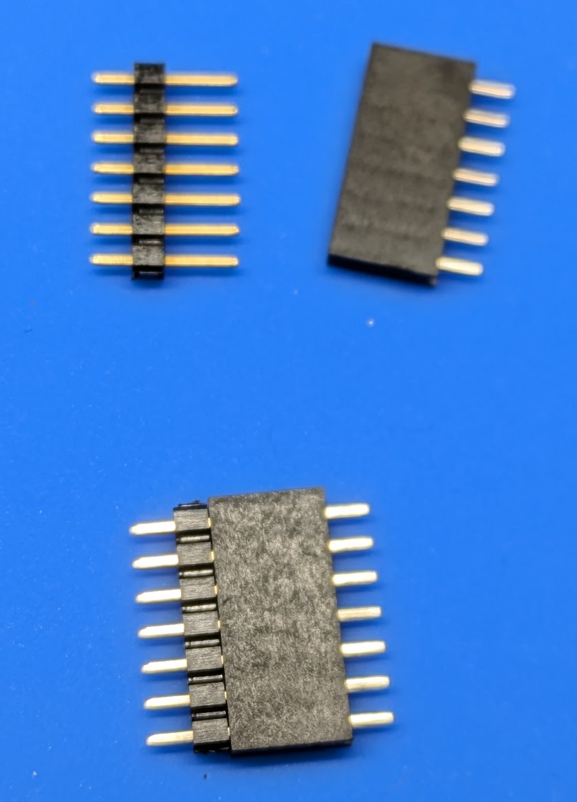
Solder Pin Sockets, Pin Headers, and MCU. 1st, combine Pin Sockets and Headers as show below:
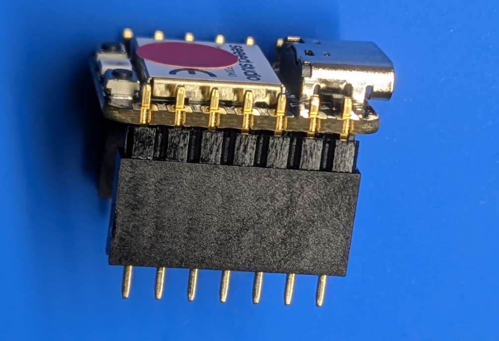
Put above result into MCU's both side holes as shown below:
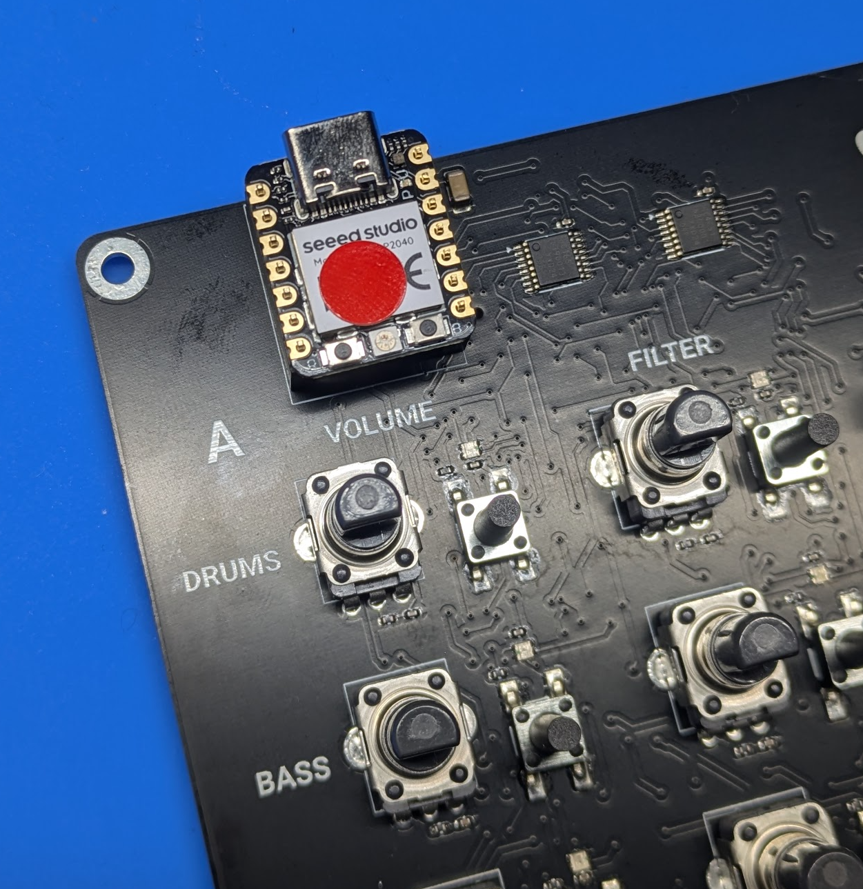
Put them on the holes of PCBA below:
Solder the Pin Header's MCU side:
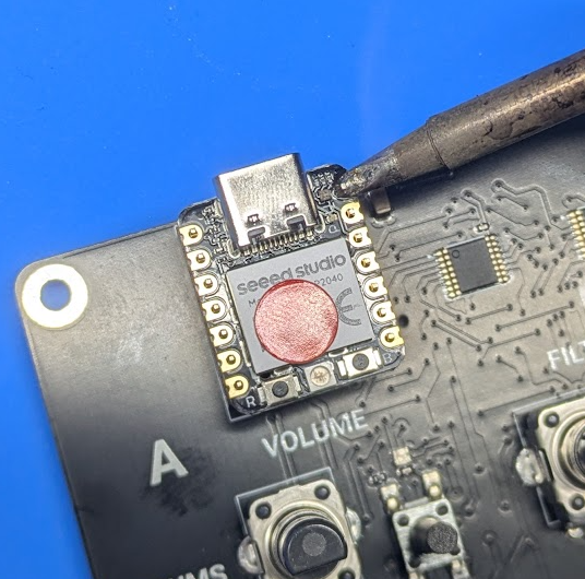
Looks like below:
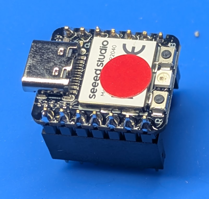
Put it again on the PCBA's holes:
Flip the PCBA board while holding the MCU module, with placing knob cap between MCU and the desk so that it can be held in place by its own weight.
Looks like below:
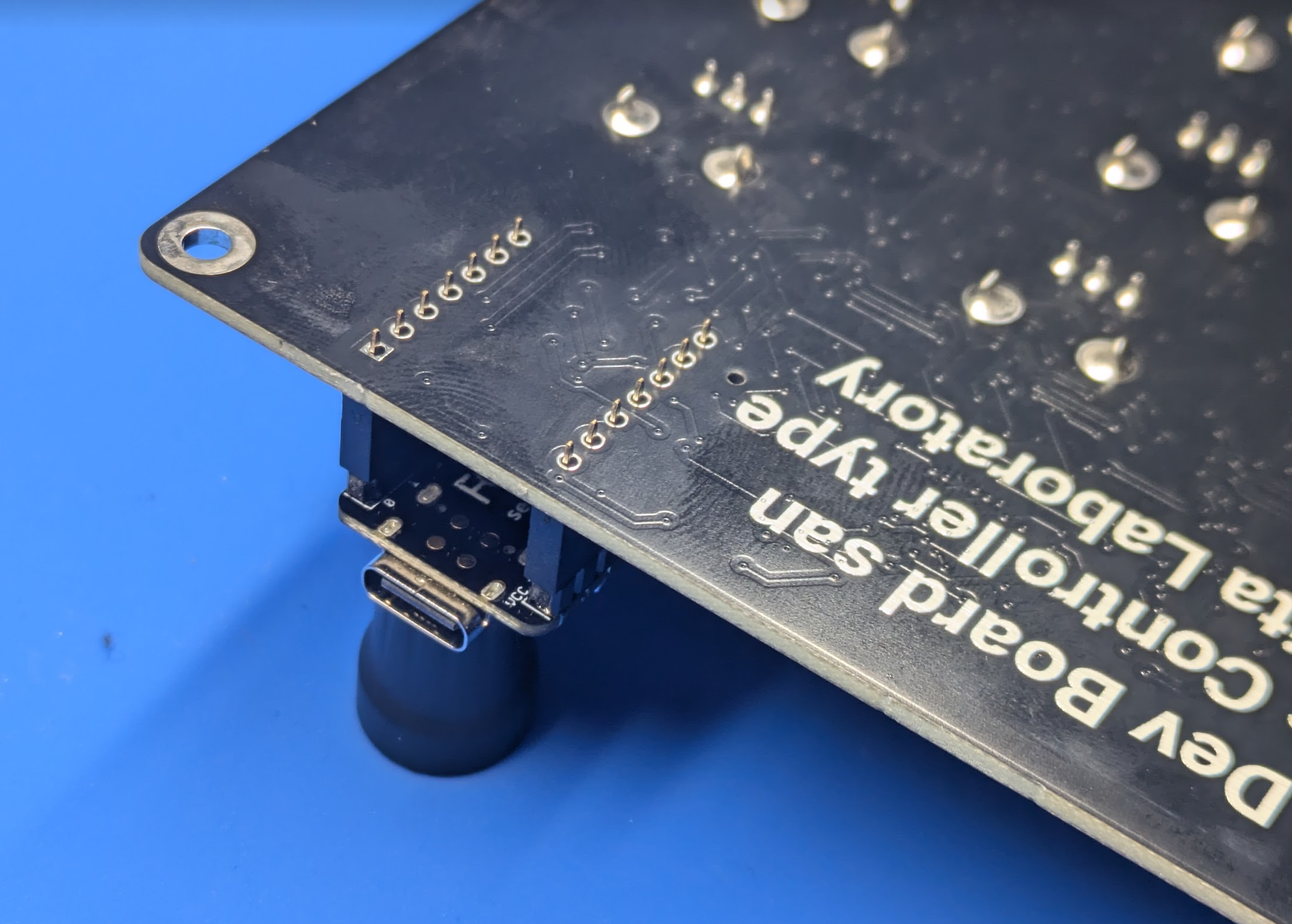
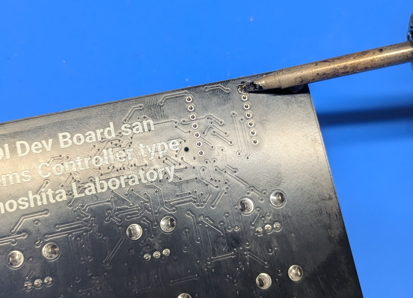
Solder all the Pin socket's pin:
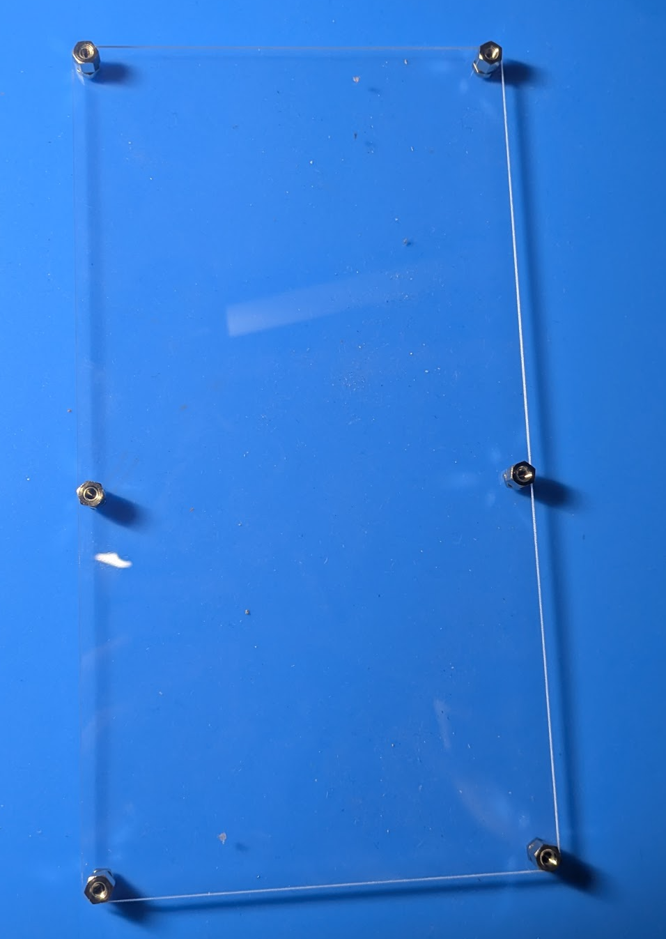
Peel off the protective sheet from the bottom acrylic panel, and attach nuts, M3 7mm Hex spacers hex screws (the shorter ones) at six locations. (There are no two sides to the acrylic.):
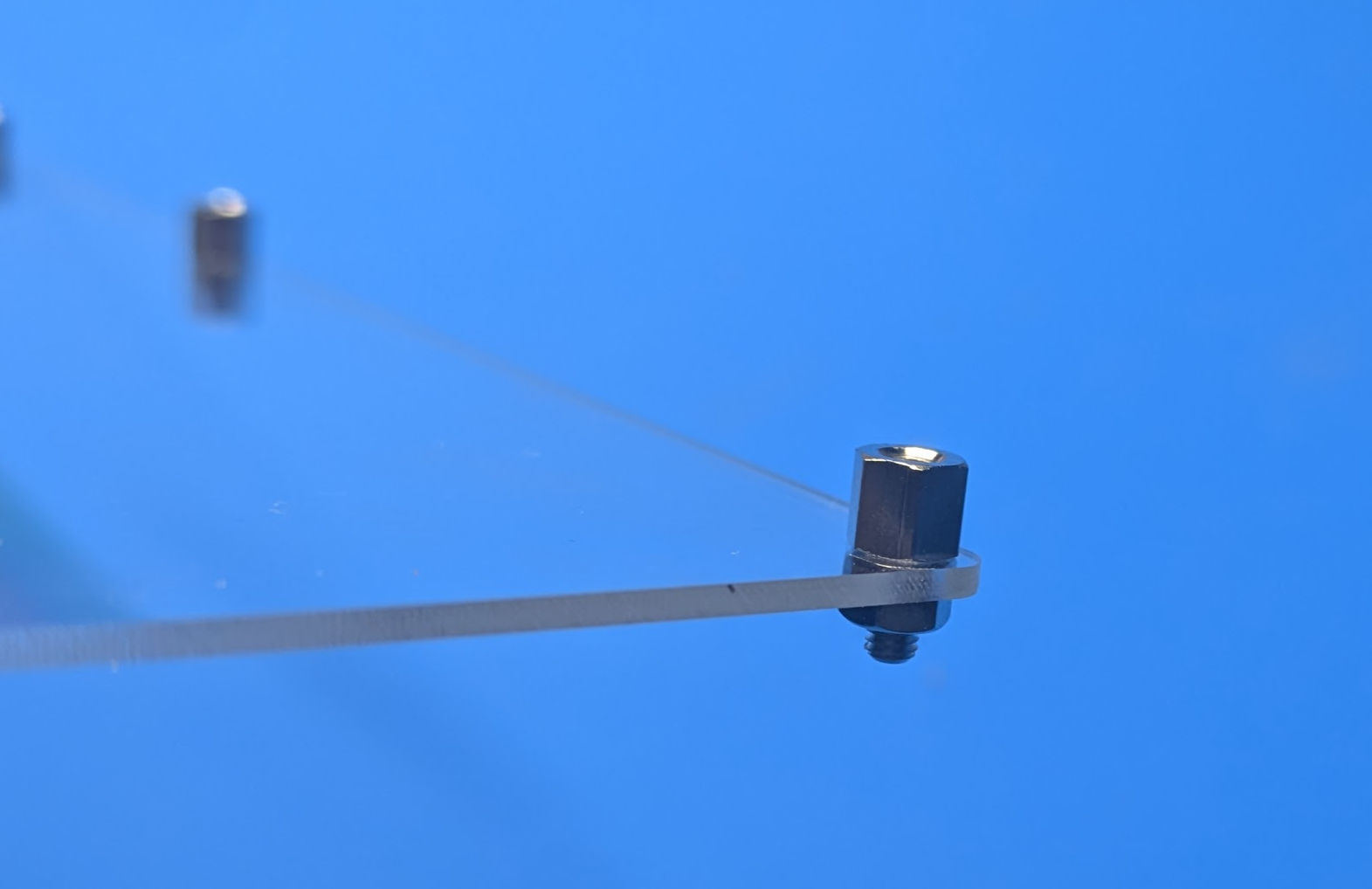
Put PCBA bord on it, tighten with the M3 10mm hex screws (the longer ones). Tighten each screw little by little at to align the overall position:
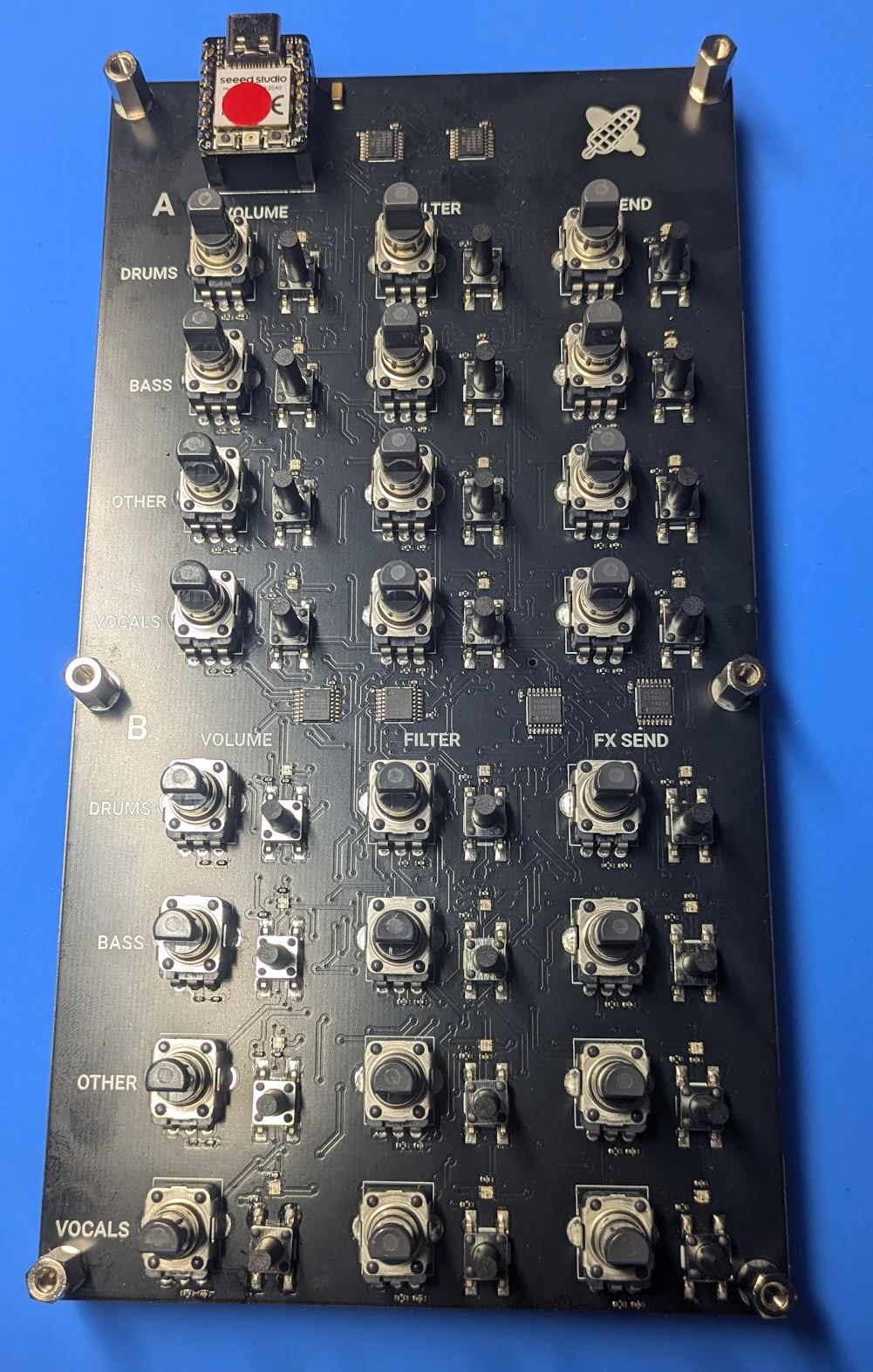
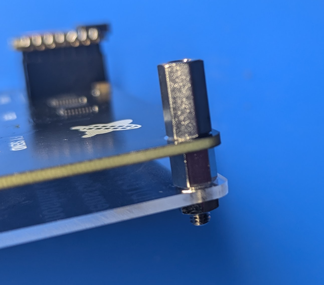
Peel of the protective sheet from top acrylic panel and put it on the PCBA. Tighten them with M3 screws. Again, tighten each screw little by little at to align the overall position:
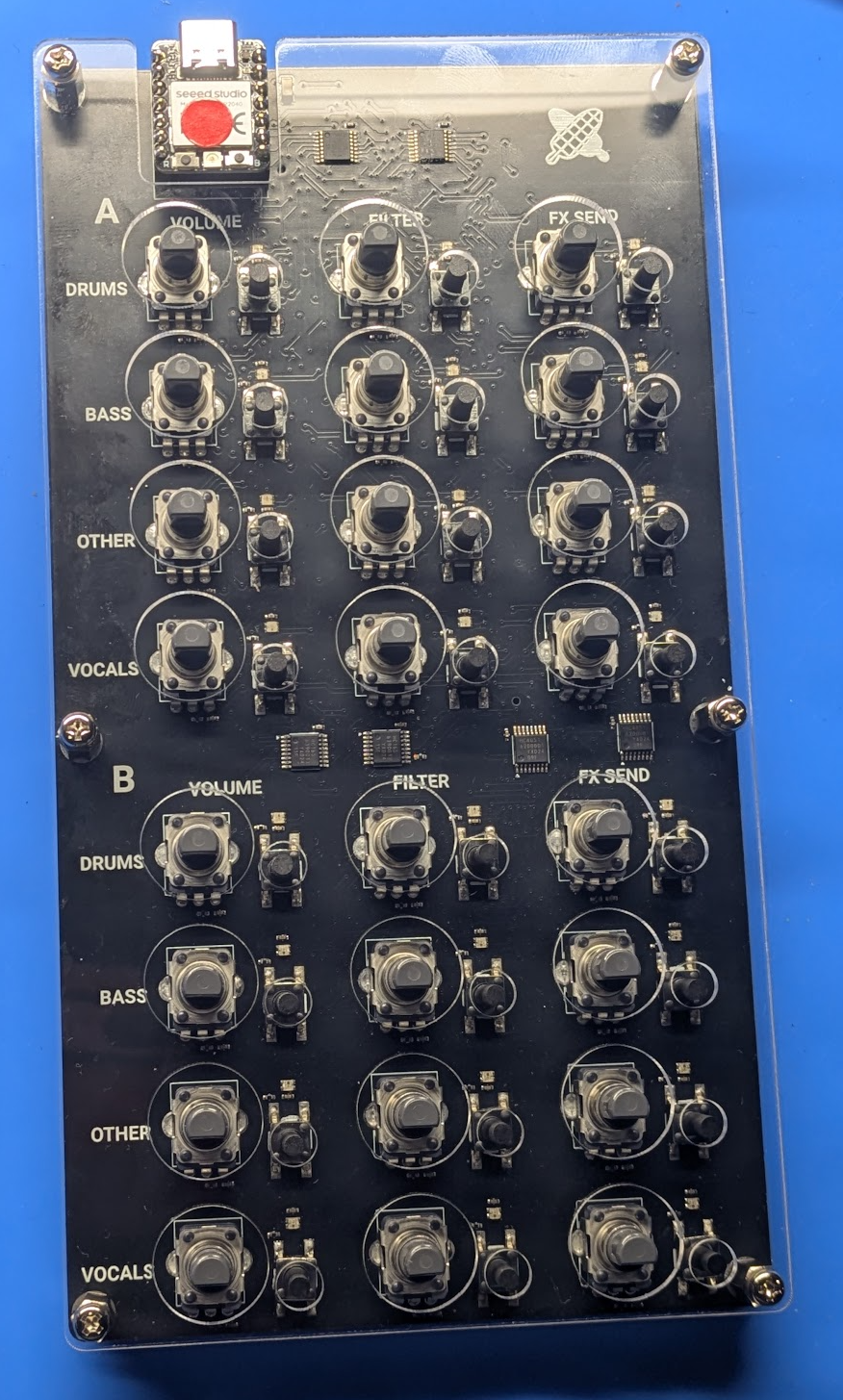
Put rubber feets on the bottom:
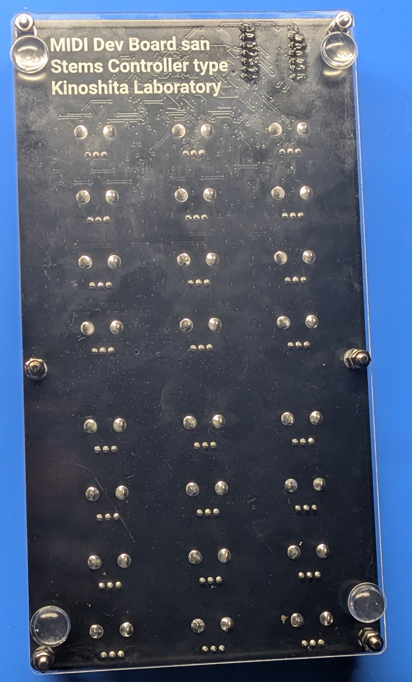
Place knob caps:
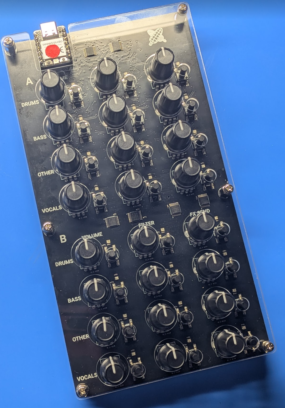
Place tactile switch caps:
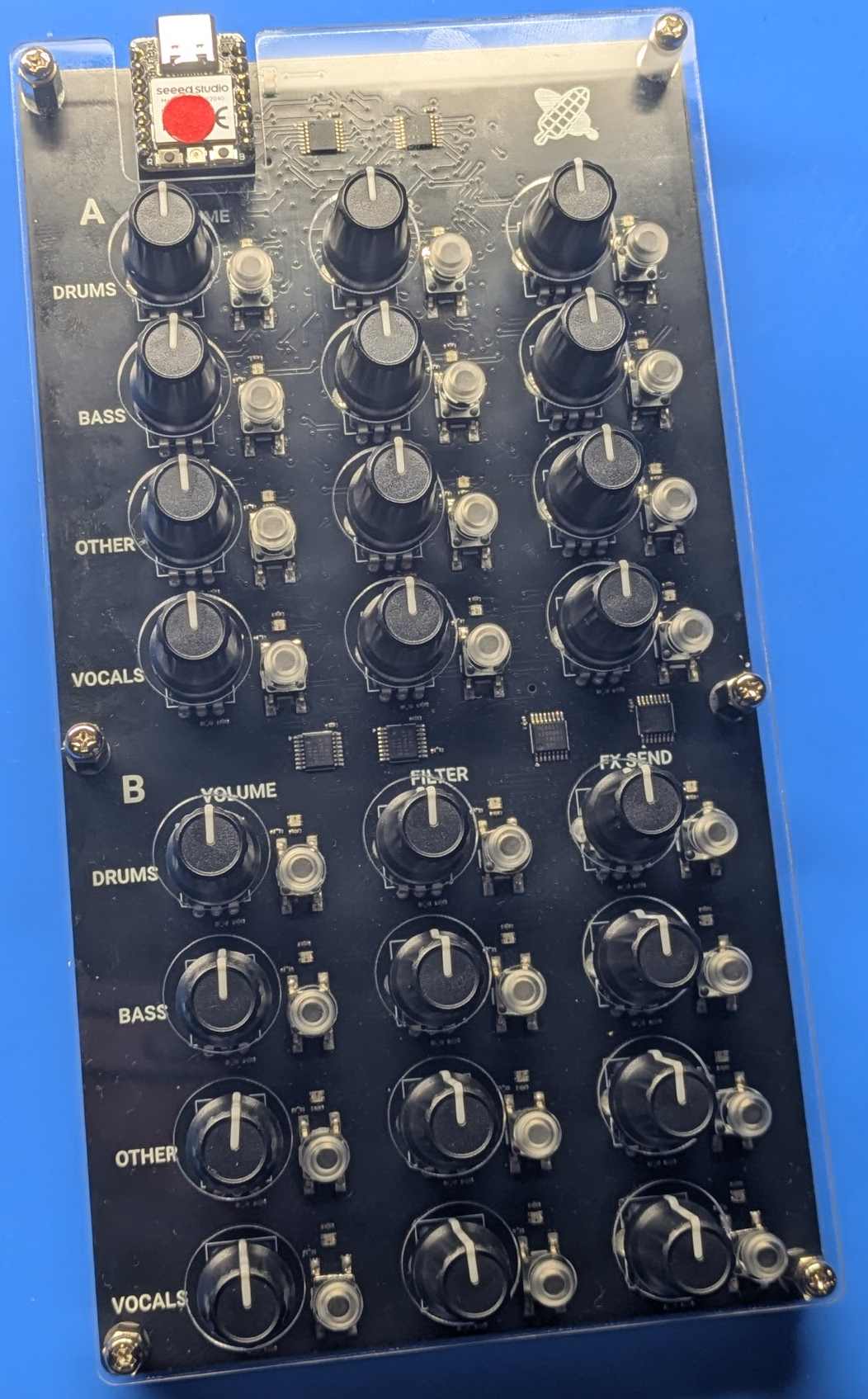
https://github.com/kinoshita-lab/StemsMIDI/tree/main/Traktor%20Setting
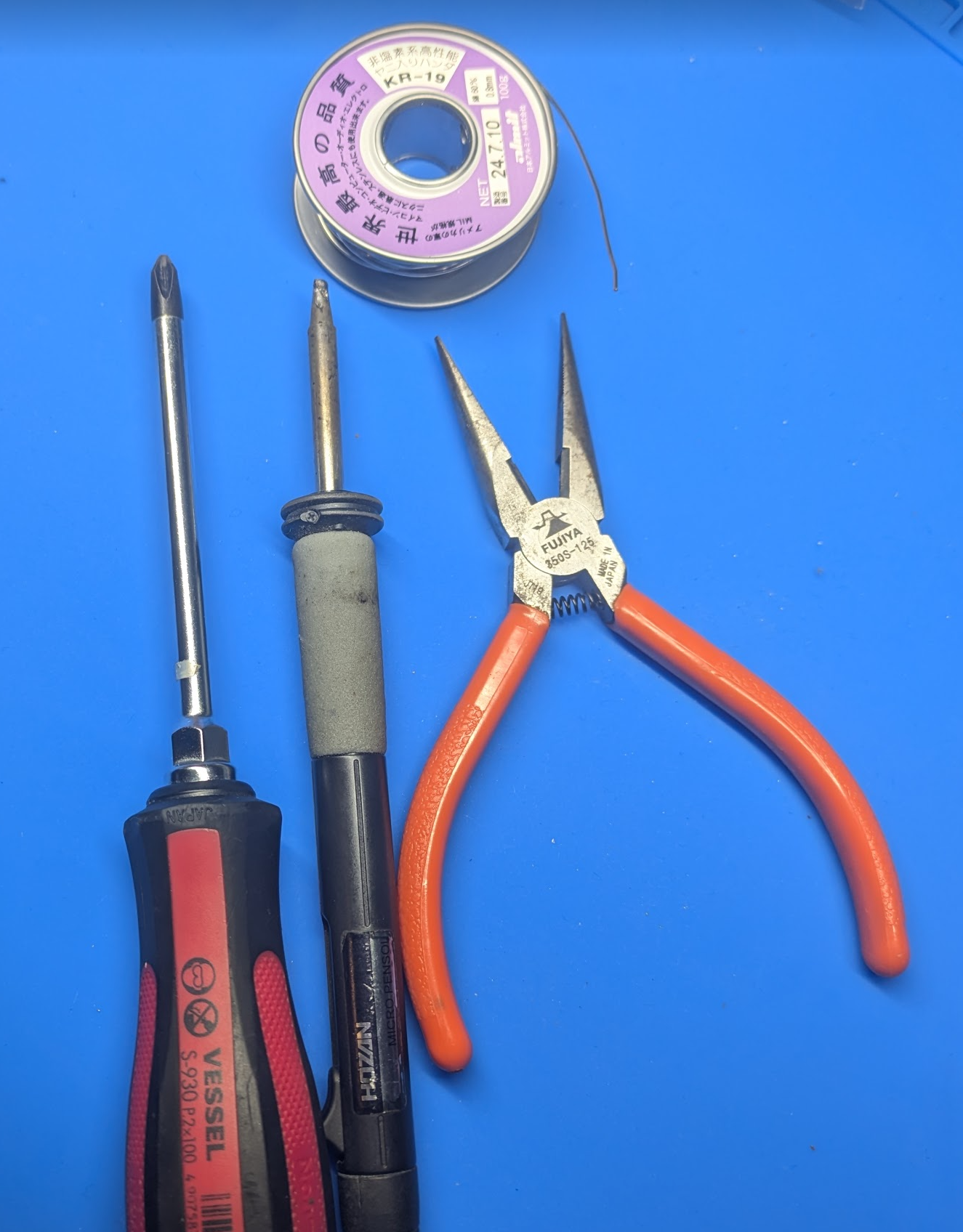
What you will need:
Connect the USB cable with pressing the B button on the right bottom of the MCU.
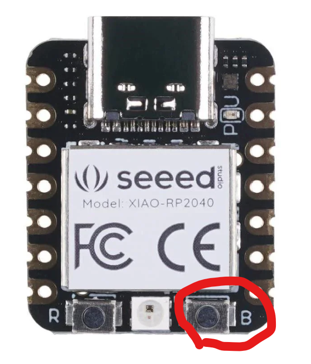
After releasing the button, disk drive will appear on you PC/mac. The drive name is RP-RP2.
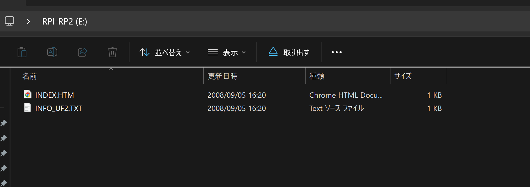
Copy the firmware.uf2 file to the drive.
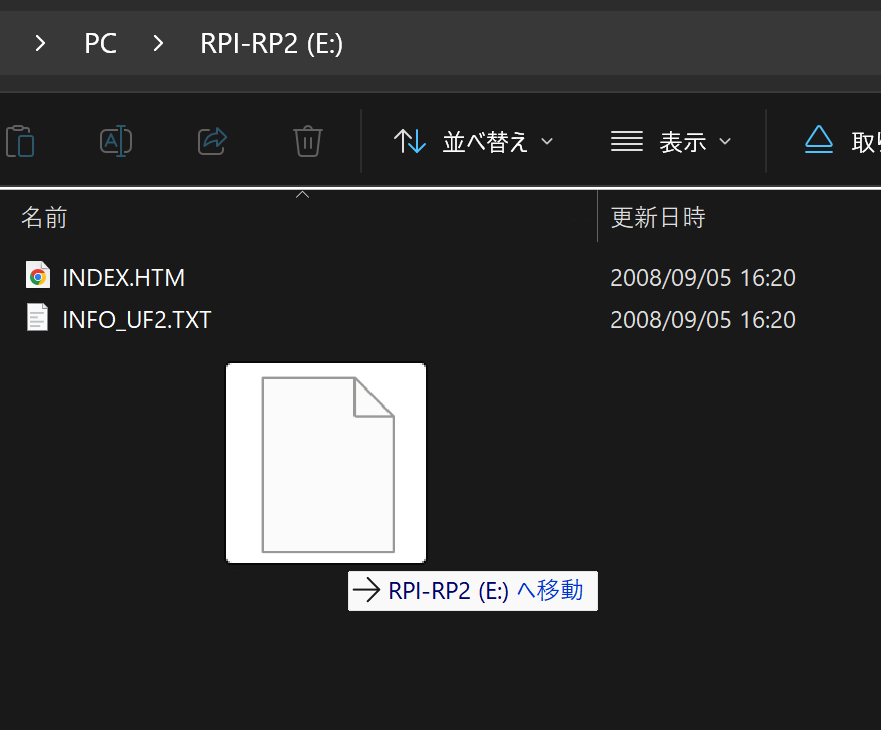
Done updating, drive will automatically closed.
| Qty | Value | Footprint | References |
|---|---|---|---|
| 54 | 100n | Capacitor_SMD:C_0402_1005Metric_Pad0.74x0.62mm_HandSolder | C1, C2, C10, C11, C12, C13, C14, C15, C16, C17, C18, C19, C20, C21, C22, C23 +38 |
| 25 | 10k | Resistor_SMD:R_0402_1005Metric_Pad0.72x0.64mm_HandSolder | R25, R26, R27, R28, R29, R30, R31, R32, R33, R34, R35, R36, R37, R38, R39, R40 +9 |
| 24 | 100 | Resistor_SMD:R_0402_1005Metric_Pad0.72x0.64mm_HandSolder | R1, R2, R10, R11, R12, R13, R14, R15, R16, R17, R18, R19, R20, R21, R22, R23 +8 |
| 24 | 10kB | my_footprint:Potentiometer_Alps_RK09K_Horizontal_CORRECTED | RV1, RV2, RV10, RV11, RV12, RV13, RV14, RV15, RV16, RV17, RV18, RV19, RV20, RV21, RV22, RV23 +8 |
| 24 | LED_NeoPixel_XL-1615RGBC-WS2812B | my_footprint:LED_NeoPixel_XL-1615RGBC-WS2812B | D1, D2, D10, D11, D12, D13, D14, D15, D16, D17, D18, D19, D20, D21, D22, D23 +8 |
| 24 | SW_SPST | my_footprint:SW_Tactile_6mm_x_6mm_Futsuuno_SMD | SW1, SW2, SW10, SW11, SW12, SW13, SW14, SW15, SW16, SW17, SW18, SW19, SW20, SW21, SW22, SW23 +8 |
| 6 | MountingHole_Pad | MountingHole:MountingHole_3.2mm_M3_Pad | H1, H2, H3, H4, H5, H6 |
| 3 | 74HC165 | Package_SO:TSSOP-16_4.4x5mm_P0.65mm | U4, U5, U6 |
| 3 | 74HC4051 | Package_SO:TSSOP-16_4.4x5mm_P0.65mm | U1, U2, U3 |
| 1 | 100u | Capacitor_SMD:C_1206_3216Metric_Pad1.33x1.80mm_HandSolder | C31 |
| 1 | Conn_02x07_Odd_Even | my_footprint:PinSocket_2x07_P2.54mm_Vertical_Flipped | J1 |
| 1 | MOUDLE-SEEEDUINO-XIAO | others:Seeduino_Xiao_RP2040_MOUDLE14P-2.54-21X17.8MM | U7 |
| 1 | logo | my_footprint:kinoshita-logo_simplified_300dpi | LOGO1 |


mcbronkowitch/fireflow
FireFlow — a modulation-first ambient groovebox: the modulation system is the instrument, not a layer on top of it. Five independent lanes per part driving a synth, granular, wavetable, resonator or bucket-brigade deck.

Mo-MoS/controllers
Controllers for MIDI, USB, Software Synths, VST Plugins.

RustyCircuit/grid-devkit
KiCad PCB designed to interoperate with the Intech Studio Grid ecosystem. This devkit is a fork of Intech's VSNX hardware design, adapted to fill a gap between fully-developed hardware and breadboard/DIY controller…

ManuelArgibay/Industrial-I-O-Controller
Industrial 24V I/O controller featuring protected high-side and low-side outputs, multiplexed analog and digital inputs, and MCU-based control.


fossasia/pslab-hardware
PSLab Hardware Design and Schematics https://pslab.io
It measures 105 × 195 mm and has 2 copper layers, 1.6 mm thick.
191 parts, built around the 74HC165D and 74HC4051. The full list of its parts is on this page, with links to each part's symbol and footprint where PCBKit's library has them.
From the kinoshita-lab/StemsMIDI repository on GitHub, at the commit this page was made from: the board is hard/StemsMIDI.kicad_pcb and its schematic hard/StemsMIDI.kicad_sch. PCBKit opens the board in the browser, with nothing to install.
Its repository publishes it under the MIT licence: you may reuse it on that licence's terms (keep the author's notice, and for a copyleft licence share your changes alike).