2 layers43.5 × 40.7 mm
TR Switch
kholia/Simple-TR-Switch
VU3CER's non-RF-sensing, MCU controlled Simple T/R Switch with RX Grounding!
18 parts11

 kholia/Simple-TR-Switch11
VU3CER's non-RF-sensing, MCU controlled Simple T/R Switch with RX Grounding!
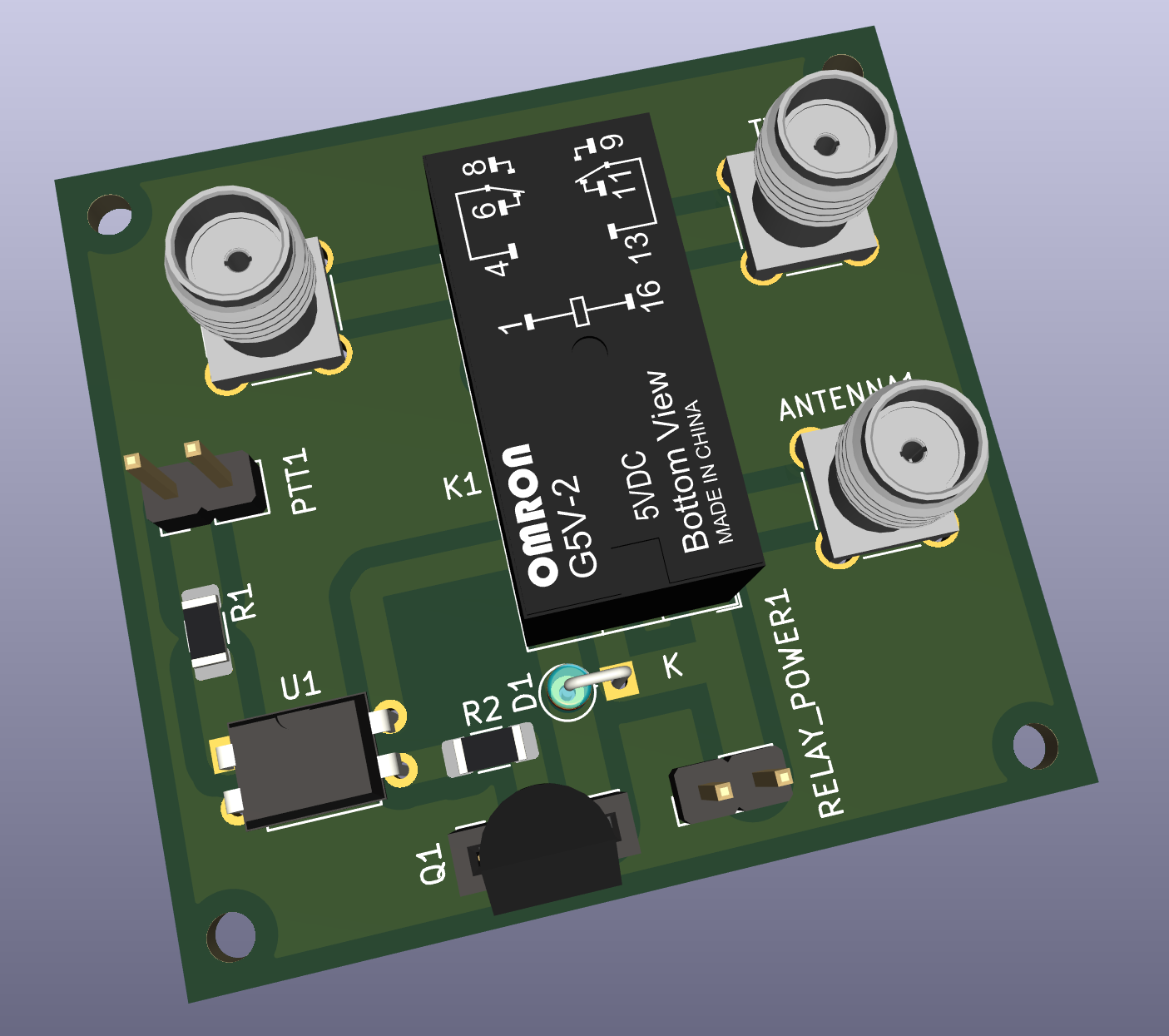
TR Switch is an open-source printed circuit board by kholia, from the kholia/Simple-TR-Switch repository on GitHub. It is a 2-layer board of 43.5 × 40.7 mm with 15 parts on 11 nets, routed with 34 tracks and 0 vias.
Its parts include 2 resistors, 1 IC, 1 diode, 1 transistor and 1 switch. It belongs with the radio and wireless boards of this library.
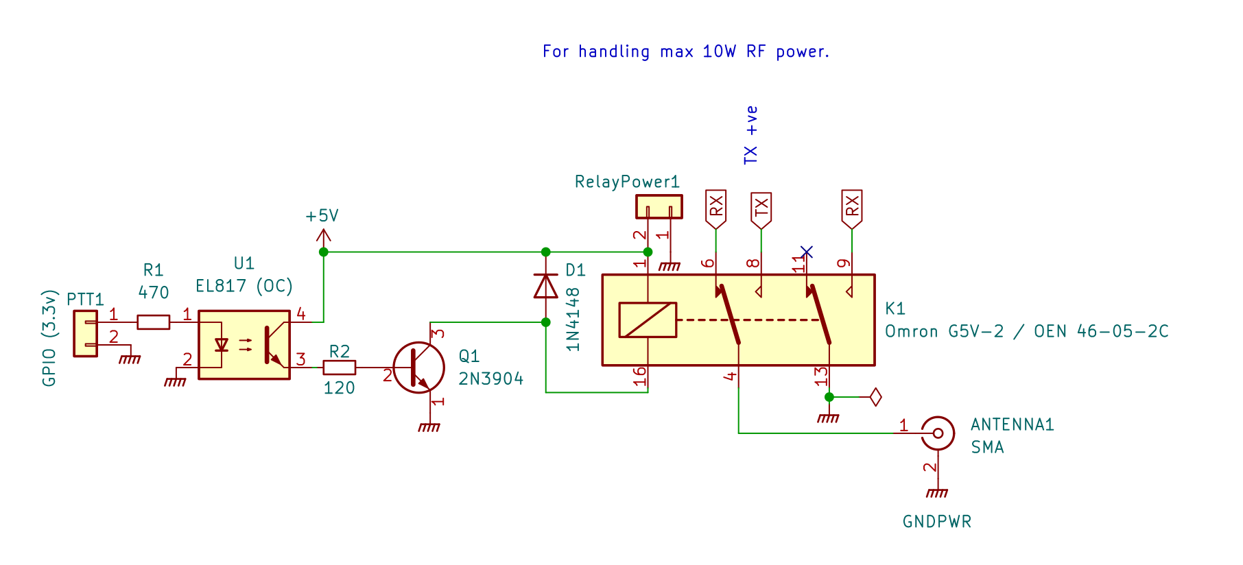
This is a non-RF-sensing, MCU PTT-controlled Simple T/R Switch with RX
Grounding feature which can be built for less than 2 dollars!
It was designed, and tested for https://github.com/kholia/Easy-Transceiver project.
TX power is 10W from IC-705 operating in FM mode.
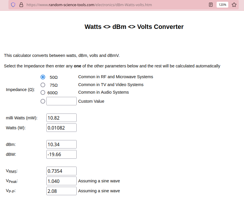
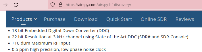
With a 2-channel relay as a T/R switch, when both RX Ground and Center are disconnected and left floating, a voltage of around ~2.2v is induced across RX connections which is unsafe for typical SDRs.
~2.2 Vpp is 10.93 dBm!
https://www.random-science-tools.com/electronics/dBm-Watts-volts.htm
With a 1-channel relay as a T/R switch which is switching the Center
connection only, and with all Grounds (TX, RX, Antenna) shorted, a voltage of
around ~1.66v is induced across RX connections which is theoretically safe
for common SDRs.
With a 2-channel relay as a T/R switch, with all Grounds (TX, RX, Antenna)
shorted, with Center switching using Channel 1, and RX Center Grounding
using Channel 2 during TX, a voltage of around ~500mV is induced across RX
connections which should be fine for most common SDRs.
No external 12v power is needed unlike Easy TR Switch from https://www.qrpkits.com/ezseries.html.
The ~4000 INR SDR Transceiver and Receiver Switch Antenna Sharer TR Switch Box 160 MHz from Banggood doesn't work in Automatic Mode if there is
Broadcast/SW Interference in your area. The Banggood TR switch switches on
the RTX (red) and disconnects the SDR (RX) as soon as the antenna is connected
under BCI conditions, when operating in Automatic Mode.
5V 2A DPDT OEN MICRO RELAY 46-05-2C
Here is another additional mechanism to protect sensitive SDRs.
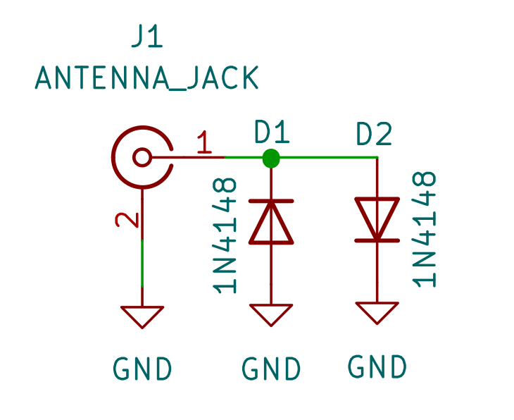
This is OK for HF (shortwave).
Solid switching using BS170 could be another option.
The info folder has more information on this.
Thanks to VU2ASH (Ashok Joshi), K.P.S. Kang, and LW1ECP (Daniel Alonso) for all the help.
https://circuits-diy.com/optocoupler-relay-driver-with-pc817-2n3904/
| Qty | Value | Footprint | References |
|---|---|---|---|
| 4 | MountingHole | MountingHole:MountingHole_2.2mm_M2 | H1, H2, H3, H4 |
| 3 | SMA | Connector_Coaxial:SMA_Amphenol_901-144_Vertical | ANTENNA1, RX1, TX1 |
| 1 | 120 | Resistor_SMD:R_1206_3216Metric_Pad1.30x1.75mm_HandSolder | R2 |
| 1 | 1N4148 | Diode_THT:D_DO-35_SOD27_P2.54mm_Vertical_KathodeUp | D1 |
| 1 | 2N3904 | Connector_PinSocket_2.54mm:PinSocket_1x03_P2.54mm_Vertical | Q1 |
| 1 | 470 | Resistor_SMD:R_1206_3216Metric_Pad1.30x1.75mm_HandSolder | R1 |
| 1 | EL817 (OC) | Package_DIP:DIP-4_W7.62mm | U1 |
| 1 | GPIO (3.3v) | Connector_PinHeader_2.54mm:PinHeader_1x02_P2.54mm_Vertical | PTT1 |
| 1 | Omron G5V-2 / OEN 46-05-2C | Relay_THT:Relay_DPDT_Omron_G5V-2 | K1 |
| 1 | RelayPower1 | Connector_PinHeader_2.54mm:PinHeader_1x02_P2.54mm_Vertical | RELAY_POWER1 |
It measures 43.5 × 40.7 mm and has 2 copper layers, 1.6 mm thick.
15 parts. The full list of its parts is on this page, with links to each part's symbol and footprint where PCBKit's library has them.
From the kholia/Simple-TR-Switch repository on GitHub, at the commit this page was made from: the board is v2/TR-Switch.kicad_pcb and its schematic RF-Limiter/RF-Limiter.kicad_sch. PCBKit opens the board in the browser, with nothing to install.
Its repository states no licence, so its author keeps all rights: ask kholia before reusing the design.
kholia/Simple-TR-Switch
VU3CER's non-RF-sensing, MCU controlled Simple T/R Switch with RX Grounding!

kholia/Simple-TR-Switch
VU3CER's non-RF-sensing, MCU controlled Simple T/R Switch with RX Grounding!

kholia/Simple-TR-Switch
VU3CER's non-RF-sensing, MCU controlled Simple T/R Switch with RX Grounding!

google/mozc-devices
Circuit diagrams and firmware source code for Gboard DIY keyboards

hoglet67/RGBtoHDMI
Bare-metal Raspberry Pi project that provides pixel-perfect sampling of Retro Computer RGB/YUV video and conversion to HDMI

mntmn/amiga2000-gfxcard
MNT VA2000, an Open Source Amiga 2/3/4000 Graphics Card (Zorro II/III), written in Verilog

hackclub/OnBoard
💡 Join 1,000 teenagers and make your first PCB with a $100 grant!

kenp-io/not-for-airpods-repairs
The content of this repository is licensed under the WTFPL License. Please have a close look at the terms before using this material.

Luos-io/luos_engine
Open-source and real-time orchestrator for cyber-physical-systems, to easily design, test and deploy embedded applications and digital twins.

Chrismettal/EleLab_v2
Cheap DIY lab system for hobbyists and the tinkering folk
