
2 layers95.4 × 92.4 mm
Panelized
kholia/ConsensusBasedTimeSync
A portable, efficient, passive, consensus based (relative) time synchronization mechanism over radio waves. Cost-effective radio receivers too!
326 parts7

A portable, efficient, passive, consensus based (relative) time synchronization mechanism over radio waves. Cost-effective radio receivers too!
BoB is an open-source printed circuit board by kholia, from the kholia/ConsensusBasedTimeSync repository on GitHub. It is a 2-layer board of 60.5 × 36.1 mm with 42 parts on 26 nets, routed with 178 tracks and 105 vias.
It is built around the MCP6002-I/P and CD4148WSP. Its parts include 18 capacitors, 5 resistors, 3 ICs, 2 diodes and 2 connectors. It belongs with the radio and wireless boards of this library.


We present a portable, efficient, passive, consensus based (relative) time synchronization mechanism over radio waves.
We demonstrate the portability of this mechanism on a bunch of common computing platforms:
AMD64 PCs
Raspberry Pi(s)
Android phones
Raspberry Pi Pico (Yep!)
FT8, WSPR, and other digital modes need the receivers and the transmitters to be synchronized in time.
What if there is no external and reliable reference available for time synchronization?
RTC clocks can drift over time.
GPS system can be jammed.
In comparison, a passive receiver system (i.e. our system) operating over a wide range of amateur radio frequencies may be a bit harder to jam.
Internet may NOT be available in remote areas.
Sundials can be cumbersome to deploy, calibrate, and perhaps not accurate enough ;)
Problem Statement: How do we ensure that we are still able to communicate over amateur bands using time-synchronized digital modes in absence of external and reliable references of time?
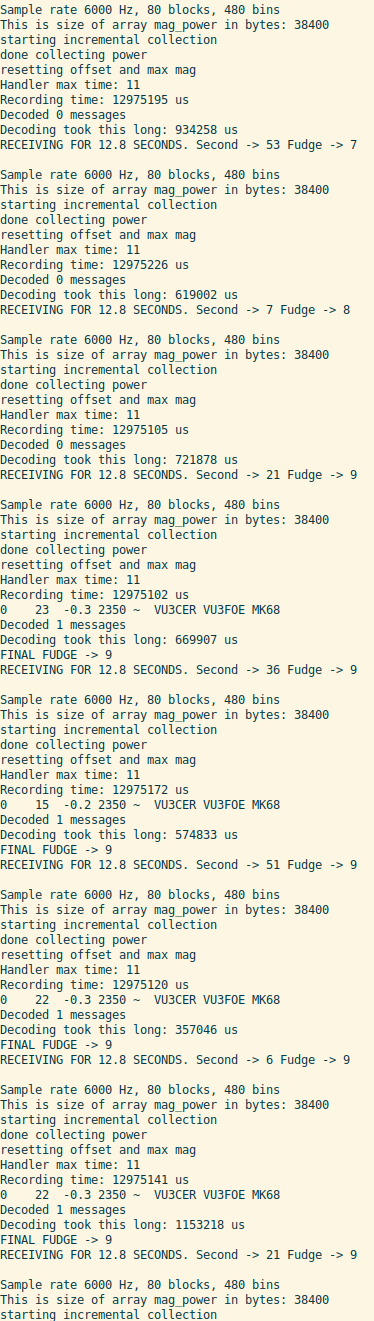
Initially, we don't know the (relative) time. We try to decode FT8 traffic with
a timing fudge factor of 0. If we don't succeed to decode any traffic, this
fudge factor is incremented. This process is repeated until we are able to
decode FT8 traffic successfully. The final value of the fudge factor gives
us the (relative) time offset we need.
We use Si4732-A10 IC for HF SSB reception. The Si5351 module provides a clock output to this Si4732-A10 IC. The other outputs of the Si5351 module can be used to implement a transmitter.
Thus the whole system is actually a low cost, portable, and efficient digital transceiver!
The whole system is beginner friendly, and can be built easily on a breadboard in under an hour or so.
The Si4732-A10 IC is fairly easy to solder on a SMD-To-DIP adapter PCB - no need to worry about it ;)
For a low-cost alternate option to Si4732-A10, checkout the CD2003 option
included in this repository.
Tip: Use KiCad 7.x for handling these designs.
Update (September 2023): After on-air testing, we recommend building the
CD2003-BoB-v2 design included in this repository over other designs for HF!
The CD2003-S-BoB design works too but BFO frequency tuning seems like a hard,
finicky process.
Update 2 (November 2023): Please use the CD2003-BoB-Final version. It has
some minor correctness fixes in it.
Update 3 (March 2024): Please use the CD2003-BoB-Final-v2 version. It can be
automatically assembled by JLCPCB!
ATTENTION: The Si4732 IC uses 3.3v signaling! Don't attach it to a 5v MCU without a bi-directional level shifter.
For sample programs, see https://github.com/pu2clr/SI4735/tree/master/examples.
We include a fully-functional FT8 receiver firmware (for Raspberry Pi Pico) in
this repository. It works on 20m (14.074 MHz) by default. To use this firmware,
write firmware/run_ft8.uf2 to a Raspberry Pi Pico board.
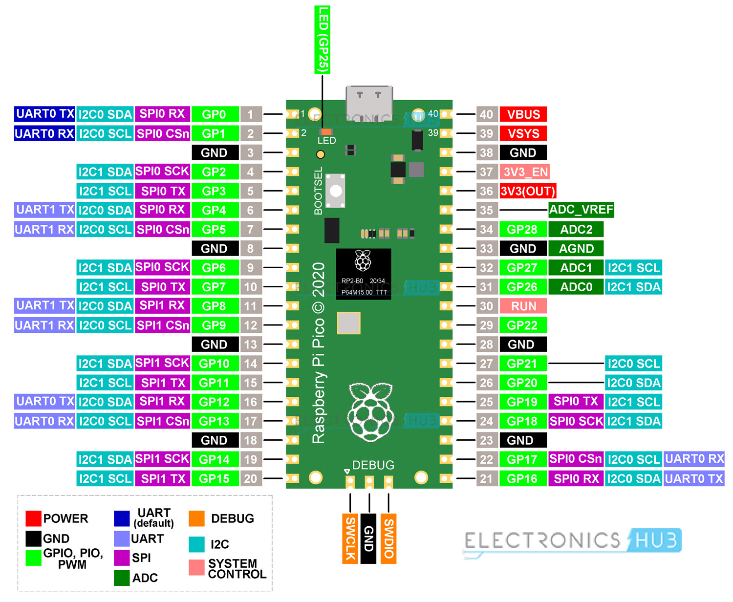
#define CAL            15 // Automatic calibration entry
#define SDA_PIN        12 // GP12 on Pico
#define SCL_PIN        13 // GP13 on Pico
#define RESET_PIN      10 // GP10, Si4732 stuff
Si5351 module's CLK 0 goes to RX_OSC of Si4732. This has the 32.768 kHz clock
on it.
Si5351 module's CLK 2 goes to GP15 (CAL) of Pico. This is used for automatic calibration of Si5351 module.
Audio output comes from L and R pins of the Si4732 BoB.
https://en.wikipedia.org/wiki/Standing_on_the_shoulders_of_giants
https://github.com/kgoba/ft8_lib - We use this for FT8 decoding
https://github.com/aa1gd/pico_ft8_xcvr - Godwin demonstrated ft8_lib powered FT8 decoding on Pico first!
Bradshaw Lupton - For suggesting the original idea and pushing me to do it!
JTSync and JS8Call are capable of doing time synchronization but they are NOT portable enough and can't run on microcontrollers!
We are also interested in automatic, microcontroller based (full) time synchronization systems powered by WWV and other time sources.
And of course, we will be using DT values from the decoded FT8 traffic to derive a more accurate fudge factor soon!
| Qty | Value | Footprint | References |
|---|---|---|---|
| 8 | 100n | Capacitor_SMD:C_1206_3216Metric_Pad1.33x1.80mm_HandSolder | C2, C4, C5, C8, C9, C10, C12, C21 |
| 5 | 10u | Capacitor_SMD:C_1206_3216Metric_Pad1.33x1.80mm_HandSolder | C1, C3, C6, C13, C14 |
| 4 | MountingHole_Pad | MountingHole:MountingHole_2.2mm_M2_Pad | H1, H2, H3, H4 |
| 2 | 10k | Resistor_SMD:R_1206_3216Metric_Pad1.30x1.75mm_HandSolder | R1, R2 |
| 2 | 1k | Resistor_SMD:R_1206_3216Metric_Pad1.30x1.75mm_HandSolder | R13, Rin1 |
| 2 | 1u | Capacitor_SMD:C_1206_3216Metric_Pad1.33x1.80mm_HandSolder | C18, C19 |
| 2 | CD4148WS | PCM_Diode_SMD_AKL:D_0805_2012Metric | D7, D8 |
| 1 | 10u | Capacitor_SMD:C_1206_3216Metric_Pad1.33x1.80mm_HandSolder | C16 |
| 1 | 100 | Resistor_SMD:R_1206_3216Metric_Pad1.30x1.75mm_HandSolder | R14 |
| 1 | 100k | Connector_PinHeader_2.54mm:PinHeader_1x03_P2.54mm_Vertical | GAIN1 |
| 1 | 100uH | Inductor_SMD:L_1206_3216Metric_Pad1.22x1.90mm_HandSolder | L2 |
| 1 | 10k | Connector_PinHeader_2.54mm:PinHeader_1x03_P2.54mm_Vertical | RV1 |
| 1 | 10n | Capacitor_SMD:C_1206_3216Metric_Pad1.33x1.80mm_HandSolder | C17 |
| 1 | 1uH | Inductor_SMD:L_1206_3216Metric_Pad1.22x1.90mm_HandSolder | L1 |
| 1 | 680p | Capacitor_SMD:C_1206_3216Metric_Pad1.33x1.80mm_HandSolder | C11 |
| 1 | CD2003GB_GP | Package_DIP:DIP-16_W7.62mm_Socket | U1 |
| 1 | Conn_01x02 | Connector_PinHeader_2.54mm:PinHeader_1x02_P2.54mm_Vertical | J2 |
| 1 | Debug_Audio | TestPoint:TestPoint_THTPad_2.0x2.0mm_Drill1.0mm | TP1 |
| 1 | GND | TestPoint:TestPoint_THTPad_2.0x2.0mm_Drill1.0mm | TP2 |
| 1 | MCP6002 | Package_DIP:DIP-8_W7.62mm | U2 |
| 1 | Pin Header | footprints:PinSocket_1x09_P2.54mm_Vertical_Custom | JP1 |
| 1 | SMA Edge Mount | Connector_Coaxial:SMA_Samtec_SMA-J-P-X-ST-EM1_EdgeMount | J1 |
| 1 | SPEAKER | footprints:PJ-307_Modded | SPK1 |
| 1 | XC6206P332MR (662K) | Package_TO_SOT_SMD:SOT-23_Handsoldering | U4 |
It measures 60.5 × 36.1 mm and has 2 copper layers, 1.6 mm thick.
42 parts, built around the MCP6002-I/P and CD4148WSP. The full list of its parts is on this page, with links to each part's symbol and footprint where PCBKit's library has them.
From the kholia/ConsensusBasedTimeSync repository on GitHub, at the commit this page was made from: the board is CD2003-BoB-Final-v4/BoB.kicad_pcb. PCBKit opens the board in the browser, with nothing to install.
Its repository states no licence, so its author keeps all rights: ask kholia before reusing the design.
kholia/ConsensusBasedTimeSync
A portable, efficient, passive, consensus based (relative) time synchronization mechanism over radio waves. Cost-effective radio receivers too!

kholia/ConsensusBasedTimeSync
A portable, efficient, passive, consensus based (relative) time synchronization mechanism over radio waves. Cost-effective radio receivers too!

kholia/ConsensusBasedTimeSync
A portable, efficient, passive, consensus based (relative) time synchronization mechanism over radio waves. Cost-effective radio receivers too!

kholia/ConsensusBasedTimeSync
A portable, efficient, passive, consensus based (relative) time synchronization mechanism over radio waves. Cost-effective radio receivers too!

kholia/ConsensusBasedTimeSync
A portable, efficient, passive, consensus based (relative) time synchronization mechanism over radio waves. Cost-effective radio receivers too!

kholia/ConsensusBasedTimeSync
A portable, efficient, passive, consensus based (relative) time synchronization mechanism over radio waves. Cost-effective radio receivers too!

kholia/ConsensusBasedTimeSync
A portable, efficient, passive, consensus based (relative) time synchronization mechanism over radio waves. Cost-effective radio receivers too!

kholia/ConsensusBasedTimeSync
A portable, efficient, passive, consensus based (relative) time synchronization mechanism over radio waves. Cost-effective radio receivers too!

kholia/ConsensusBasedTimeSync
A portable, efficient, passive, consensus based (relative) time synchronization mechanism over radio waves. Cost-effective radio receivers too!

kholia/ConsensusBasedTimeSync
A portable, efficient, passive, consensus based (relative) time synchronization mechanism over radio waves. Cost-effective radio receivers too!

kholia/ConsensusBasedTimeSync
A portable, efficient, passive, consensus based (relative) time synchronization mechanism over radio waves. Cost-effective radio receivers too!

kholia/ConsensusBasedTimeSync
A portable, efficient, passive, consensus based (relative) time synchronization mechanism over radio waves. Cost-effective radio receivers too!

google/mozc-devices
Circuit diagrams and firmware source code for Gboard DIY keyboards

Camsu04/Camila_Fernandez_Electiva_2025_C2
Desarrollo de proyectos de diseño mecatronico Electiva


GaudiLabs/OpenLaserScanningMicroscope
Open Source Laser Scanning Microscope


GuitarML/GuitarPedalSTM32
Guitar pedal using a stm32h7 microcontroller programmed with CubeIDE (PCB and Firmware)

thawney/PedalPiV2
Pedal Pi V2 by Thawney is an all new and regularly maintained Pedal-Pi by electrosmash; a lo-fi programmable guitar pedal that works with the Raspberry Pi ZERO Board.

CCHS-Melbourne/ESPlant
Environmental Sensor Plant - solar WiFi gardening/meteorological sensor using ESP8266