2 layers17.8 × 35.6 mm

 kgl2001/VideoULA_V021
VideoULA replacement for BBC Micro - 64 pin XC9572XL version
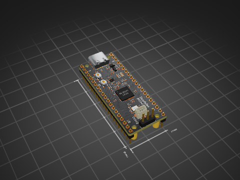
VideoULA is an open-source printed circuit board by kgl2001, from the kgl2001/VideoULA_V02 repository on GitHub. It is a 2-layer board of 17.8 × 35.6 mm with 26 parts on 82 nets, routed with 585 tracks and 64 vias.
It is built around the IS61LV256AL-10TLI and XC6206P332MR. Its parts include 11 capacitors, 5 ICs, 2 resistors, 2 connectors and 1 crystal. It belongs with the FPGA and CPLD boards of this library.


This repository contains the hardware design and firmware for the VideoULA V02, a drop-in replacement for the VC2069 Video ULA (IC6) in the Acorn BBC Micro Model B and Master 128.
The original BBC Micro Video ULA (IC6) is a custom ASIC that is no longer manufactured. Failed or missing ULAs result in a non-functional machine. This project provides a modern replacement using a CPLD and a small external SRAM for palette storage.
There are three hardware versions of this replacement, each in a separate repository:
| Version | CPLD | Macrocells | Tool | Repository |
|---|---|---|---|---|
| V01 | Xilinx XC9572XL-10-VQ44 | 72 | ISE 14.7 | VideoULA_V01 |
| V02 | Xilinx XC9572XL-10-VQ64 | 72 | ISE 14.7 | This repo |
| V03 | Atmel ATF1504AS-10AU44 | 64 | Quartus 13.0 SP1 | VideoULA_V03 |
All three versions share the same 28-pin DIP footprint as the original ULA and are pin-compatible with the BBC Micro motherboard.
| Revision | Status | Changes |
|---|---|---|
| Rev01 | PCB designed, not yet built or tested | Initial release, largely based on V01 Rev03 |
| Rev02 | PCB designed, not yet built or tested | Repositioned JTAG header |
Note: Neither revision has been built or tested. The V02 design incorporates all improvements identified during V01 testing.
The firmware is written in Verilog and built using Xilinx ISE 14.7. The same Verilog source file (src/VideoULA.v) is shared between V02 and V03.
Two firmware builds are required — one per operating mode. Both CLK_16M and CLK_48M are wired to dedicated GCK pins, so no solder bridge changes are needed to switch modes — simply reprogram the CPLD with the appropriate .jed file.
`define CLK_48MHZ in VideoULA.v`define CLK_16MHZ in VideoULA.v| Setting | Value | Notes |
|---|---|---|
| Implementation Template | Optimise Speed | Density causes timing failures at temperature |
| Macrocell Power | Std | Low Power prevents BBC from booting |
| Output Slew Rate | Fast | |
| Default Powerup Value | Low |
XC9572XL-10-VQ64src/VideoULA.v and src/VideoULA.ucf to the projectdefine in VideoULA.vImplement Design to generate the .jed fileThe external SRAM stores the 16-entry colour palette (4 bits per entry):
| SRAM Pin | Connection |
|---|---|
| A0-A3 | CPLD SRAM_ADDR[0:3] |
| A4-A14 | GND (tie low) |
| D0-D3 | CPLD SRAM_DATA[0:3] (bidirectional) |
| D4-D7 | Leave unconnected |
| /WE | CPLD SRAM_nWE |
| /OE | GND (always output enabled) |
| /CS | GND (always selected) |
The PCB has been designed using KiCAD V10 as a 2-layer board. It can easily be changed to a 4-layer board with GND/Power planes on the inner layers if signal integrity is a concern.
The board design includes a 5×5mm silkscreen box on the underside of the PCB. This is used by JLCPCB to position a QR code serial number. When ordering from JLCPCB:
If not using JLCPCB, the chosen fabricator will likely print the 5×5mm box as a plain white square on the PCB. To avoid this, remove the silkscreen box from the PCB design and regenerate the Gerber files before submitting.
A combined CPL (Component Placement List) and BOM (Bill of Materials) Excel file is included in the Gerbers folder. This can be used directly with the JLCPCB PCBA (PCB Assembly) service.
Note that the JLCPCB Economy PCBA process only assembles components on one side of the PCB. Select the top side for assembly — this leaves only the SRAM and its associated decoupling capacitor to be hand soldered to the underside of the board.
Designed for BBC Micro Model B and Master 128. The buffered clock outputs via 74LV6T17 provide the higher logic 1 voltage required by some Master 128 custom ICs.
Hardware: Creative Commons BY-SA 4.0
Firmware: MIT Licence
| Qty | Value | Footprint | References |
|---|---|---|---|
| 7 | 100n | Capacitor_SMD:C_0603_1608Metric | C1, C2, C3, C4, C7, C8, C11 |
| 2 | 10K | Resistor_SMD:R_Array_Convex_4x0603 | RN1, RN2 |
| 2 | 10u | Capacitor_SMD:C_0603_1608Metric | C9, C10 |
| 2 | 1u | Capacitor_SMD:C_0603_1608Metric | C5, C6 |
| 1 | 10K | Resistor_SMD:R_0603_1608Metric | R2 |
| 1 | 47R | Resistor_SMD:R_0603_1608Metric | R1 |
| 1 | 48MHz | VideoULA:Oscillator_SMD_Yajingxin_TFOM48M4RHKCNT2T-4Pin_3.2x2.5mm | X1 |
| 1 | 74LV6T17 | Package_DFN_QFN:DHWQFN-14-1EP_2.5x3mm_P0.5mm_EP1x1.5mm_ThermalVias | U3 |
| 1 | Conn_01x01 | Connector_PinHeader_2.54mm:PinHeader_1x01_P2.54mm_Horizontal | J2 |
| 1 | IS61LV256AL-10TLI | VideoULA:TSOP-I-28_11.8x8mm_P0.55mm_SRAM | U4 |
| 1 | JTAG-IDC | Connector_PinHeader_2.54mm:PinHeader_2x05_P2.54mm_Vertical | J1 |
| 1 | Skidog | VideoULA:skidog_inv | G1 |
| 1 | SolderJumper_2_Open | Jumper:SolderJumper-2_P1.3mm_Open_RoundedPad1.0x1.5mm | JP1 |
| 1 | SolderJumper_3_Bridged12 | Jumper:SolderJumper-3_P1.3mm_Bridged12_RoundedPad1.0x1.5mm | JP2 |
| 1 | VC2069 Socket | Package_DIP:DIP-28_W15.24mm | IC6 |
| 1 | XC6206P332MR | Package_TO_SOT_SMD:SOT-23-3 | U2 |
| 1 | XC9572XL-xxVQx64 | Package_QFP:TQFP-64_10x10mm_P0.5mm | U1 |
Hanqaqa/Easyduino
Easily dive into different PCB KiCad designs of the most popular microcontroller devboards

makeo/PicoLoader
A cheap and easy to install modchip for the Nintendo GameCube!

sd2psx/pcb
The PCB must be produced in 0.8mm thickness. Production files are provided under the "Releases" tab. These do not include the through-hole OLED module.


KarlK90/yaemk-split-kb
5x8 Split keyboard with thumb-clusters, rotary encoders and oleds.

ebastler/E80-1800
QMK compatible PCB replacement for Cherry G80-1800
It measures 17.8 × 35.6 mm and has 2 copper layers, 1.6 mm thick.
26 parts, built around the IS61LV256AL-10TLI and XC6206P332MR. The full list of its parts is on this page, with links to each part's symbol and footprint where PCBKit's library has them.
From the kgl2001/VideoULA_V02 repository on GitHub, at the commit this page was made from: the board is KiCAD Files/Rev01/VideoULA.kicad_pcb and its schematic KiCAD Files/Rev01/VideoULA.kicad_sch. PCBKit opens the board in the browser, with nothing to install.
Its repository states no licence, so its author keeps all rights: ask kgl2001 before reusing the design.