6 layers84 × 98 mm
FujiNet-5200-Rev0
FujiNetWIFI/fujinet-hardware
Schematics and design files for FujiNet hardware
145 parts142

 kgiorgi/TinyDyno
esp32-s3 based board for measuring time and energy of edge AI. Its main use is to compare my kernels to ESP-DL and TensorFlow Lite Micro on identical inputs.
TinyDyno is an open-source printed circuit board by kgiorgi, from the kgiorgi/TinyDyno repository on GitHub, published under the MIT licence. It is a 2-layer board of 72 × 72 mm with 35 parts on 53 nets, routed with 255 tracks and 55 vias.
It is built around the ESP32-S3-WROOM-1-N16R8, LSM6DS3TR-C and TS-1187A-B-A-B, with the IM69D130V01, KT-0603R and TYPE-C-31-M-12 among its other parts. Its parts include 11 capacitors, 11 resistors, 5 ICs, 2 switches and 1 diode. It belongs with the ESP32 boards of this library.


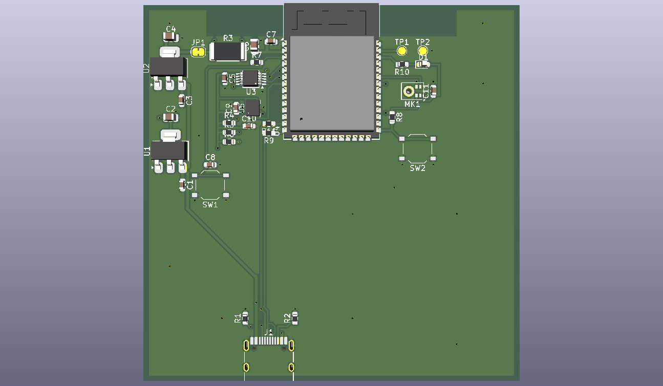
An ESP32-S3 board that measures the speed and energy efficiency of one neural network inference.
What is it exactly? TinyDyno is a custom 72 by 72 mm, 2 layered PCB based on ESP32-S3.It is basically a test bench for machine learning on tiny devices (AKA edgeAI). It runs a neural network based on the data from sensors and measures every inference for time and energy. Time is how long the inference took and energy is how much ESP32-S3 has used during it.
To account for actual use cases it has an IMU(motion sensor) and a microphone which are for gesture recognition and keyword detector so the usual run look something like this:
(A test pad (TP1) goes high during each inference, so the timing can be checked independently with an oscilloscope or logic analyzer.)
The WHY behind it all
Wanting to optimize the field I am currently curious about (AI) I brainstormed for a bit and came to the conclusion that you can't optimize something that you can't measure. After a bit of digging I found few issues it would solve on top of the qol it would provide for me:
(Also it's not like you can find stuff like this easily to buy)
how does it work?
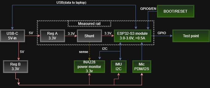
Power: two separate 3.3V rails
USB-C gives 5V and two separate 3.3V regulators split it into two rails:
So none of the sensor or LED current goes through the shunt and the measurement is only the ESP32.
Measuring power
Current going through the shunt makes a small voltage across it (V = I * R). For example at 100mA it's 0.1A * 0.075 Ohm = 7.5mV, which is tiny, so the INA226 (U3) does the job:
The shunt is read through a separate pair of thin traces that go straight from the shunt's pads to the INA226 (Kelvin sensing), so the voltage drop on the thick power traces doesn't mess up the reading.
From power to energy and time
Energy = power * time, so during an inference the ESP32 reads the power about once a millisecond and keeps adding up power * time. Time comes from the ESP32's internal microsecond timer.
One measurement looks like this:
Known problem
The ESP32 reads its own power monitor, so the reading itself costs a bit of energy too. The plan is to do the measuring on one core and the model on the other, and subtract the idle power.
Schematic and PCB
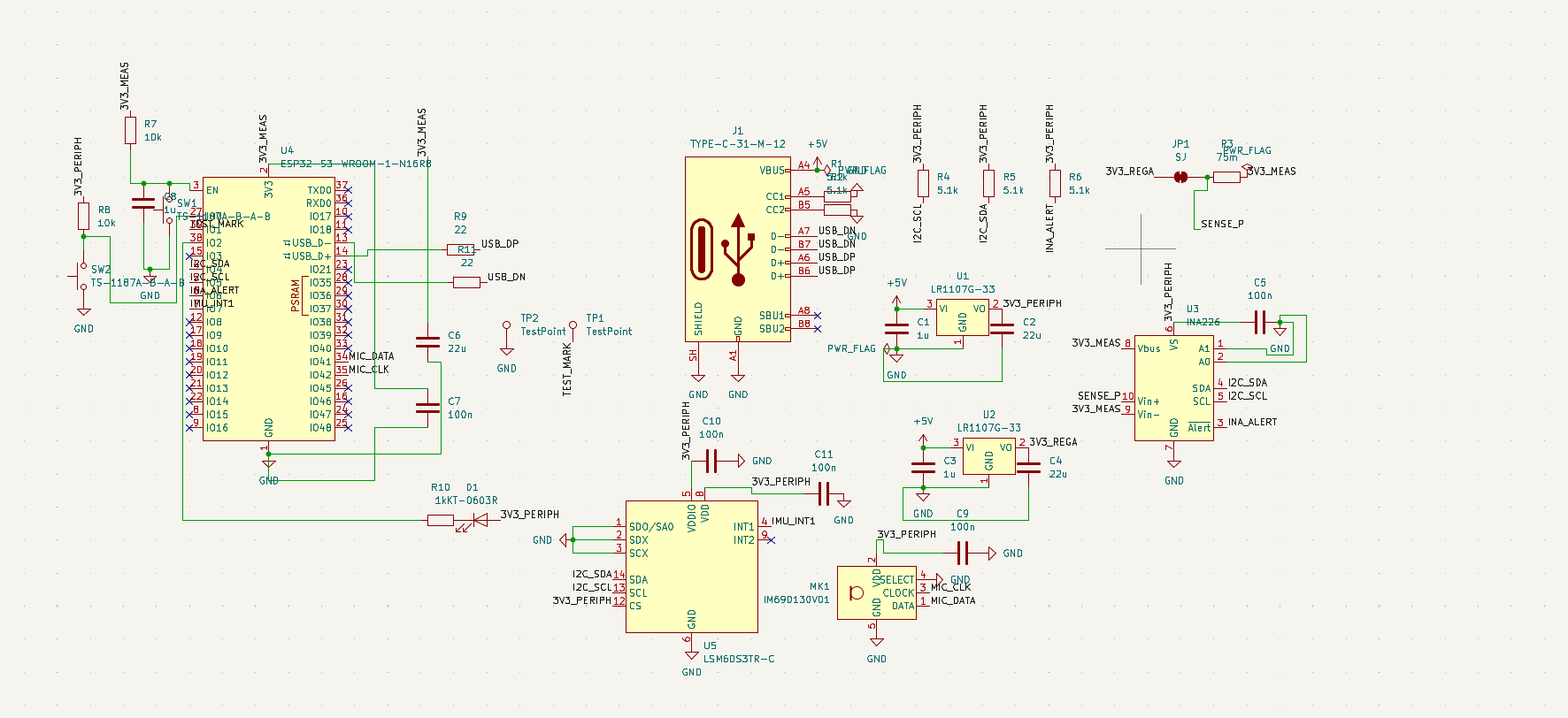
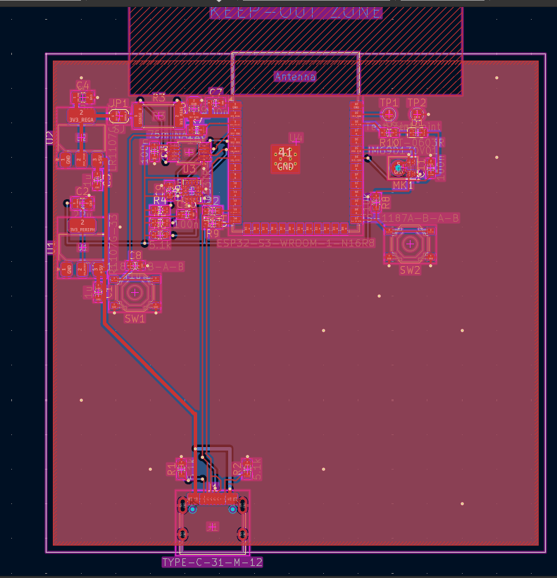
PCB design notes
Pin map
| Signal | ESP32-S3 pin |
|---|---|
| I2C SDA / SCL (INA226 and IMU) | IO4 / IO5 |
| INA226 ALERT (new reading ready) | IO6 |
| IMU interrupt (INT1) | IO7 |
| Mic DATA / CLK | IO41 / IO42 |
| Timing marker (TP1) | IO1 |
| Status LED (on when the pin is low) | IO2 |
| Boot button | IO0 |
| USB D- / D+ | IO19 / IO20 |
I2C addresses: INA226 is 0x40, IMU is 0x6A.
What it can measure (INA226 + 75 mOhm shunt)
| Item | Value |
|---|---|
| Current range | +/- 1.09A |
| Current resolution | about 33uA |
| Voltage resolution | 1.25mV |
| Fastest conversion | 140us (averaging adjustable) |
| Voltage lost across the shunt | about 37.5mV at 0.5A |
BOM (bill of materials)
Every part on the board. Everything is from LCSC and soldered by JLCPCB. Quantities are per board (2 boards get assembled).
Chips and main parts:
| Ref | Qty | Part | What it does | Package | LCSC |
|---|---|---|---|---|---|
| U4 | 1 | ESP32-S3-WROOM-1-N16R8 | Main microcontroller (16MB flash, 8MB PSRAM). Runs the models and the measuring | Module | C2913202 |
| U3 | 1 | INA226AIDGSR | Power monitor, measures current through R3 and the rail voltage | TSSOP-10 | C49851 |
| U5 | 1 | LSM6DS3TR-C | 6-axis IMU (accelerometer + gyro), input for gesture models | LGA-14 | C967633 |
| MK1 | 1 | IM69D130V01 | Digital PDM microphone, input for keyword detection | LLGA-5 | C536262 |
| U1, U2 | 2 | LR1107G-33 | 3.3V regulators. U1 is for the peripheral rail, U2 for the measured rail | SOT-223 | C171499 |
| R3 | 1 | 75 mOhm, 1%, 2512 | Shunt resistor in the ESP32's supply | 2512 | C76252 |
| J1 | 1 | TYPE-C-31-M-12 | USB-C connector, 5V and USB data | SMD | C165948 |
| SW1, SW2 | 2 | TS-1187A-B-A-B | Buttons. SW1 = reset (EN), SW2 = boot (IO0) | SMD | C318884 |
| D1 | 1 | KT-0603R red LED | Status LED | 0603 | C2286 |
Resistors:
| Ref | Qty | Value | What it does | Package | LCSC |
|---|---|---|---|---|---|
| R1, R2 | 2 | 5.1k | USB-C CC pull-downs, tell the PC/charger to give 5V | 0603 | C23186 |
| R4, R5 | 2 | 5.1k | I2C pull-ups on SCL and SDA | 0603 | C23186 |
| R6 | 1 | 5.1k | Pull-up for the INA226 ALERT line | 0603 | C23186 |
| R7 | 1 | 10k | ESP32 EN (enable) pull-up | 0603 | C25804 |
| R8 | 1 | 10k | IO0 (boot pin) pull-up so it boots normally | 0603 | C25804 |
| R9, R11 | 2 | 22 Ohm | Series resistors on USB D+ / D- | 0603 | C23345 |
| R10 | 1 | 1k | Current limit for the LED | 0603 | C21190 |
Capacitors:
| Ref | Qty | Value | What it does | Package | LCSC |
|---|---|---|---|---|---|
| C1, C3 | 2 | 1uF | Input caps of the two regulators (5V side) | 0603 | C15849 |
| C8 | 1 | 1uF | Together with R7 delays EN so the ESP32 starts cleanly | 0603 | C15849 |
| C2 | 1 | 22uF | Output cap of U1 (peripheral rail) | 0805 | C45783 |
| C4 | 1 | 22uF | Output cap of U2 (before the shunt) | 0805 | C45783 |
| C6 | 1 | 22uF | Bulk cap at the ESP32 (after the shunt), handles Wi-Fi current spikes | 0805 | C45783 |
| C7 | 1 | 100nF | Decoupling at the ESP32 power pin | 0603 | C14663 |
| C5, C9, C10, C11 | 4 | 100nF | Decoupling for the INA226, IMU and mic | 0603 | C14663 |
Not actual parts (just copper on the PCB):
| Ref | What it is |
|---|---|
| TP1 | Test pad, timing marker (high during an inference) |
| TP2 | Test pad, GND for the probe clip |
| JP1 | Solder jumper in the measured rail (closed by default) |
In total that's 32 parts per board, 16 different ones. The full exported list is in hardware/kicad/production/bom.csv, and the cost list synced from Half Life is in BOM.csv.
Cost (JLCPCB: 5 PCBs, 2 of them assembled)
| Item | Cost |
|---|---|
| PCB, 2-layer, 72 by 72mm (x5) | $4.00 |
| ESP32-S3-WROOM-1-N16R8 (x2) | $10.29 |
| IM69D130V01 microphone (x2) | $6.25 |
| LSM6DS3TR-C IMU (x2) | $3.04 |
| INA226AIDGSR (x2) | $1.52 |
| LR1107G-33 regulators | $0.86 |
| 75 mOhm shunt resistors | $0.58 |
| USB-C connectors (x2) | $0.37 |
| Resistors, capacitors, LED and buttons | $2.42 |
| Standard assembly for 2 boards (setup, stencil, part loading, placement) | $66.86 |
| Shipping situational in my case 29.82 but I cover it | covered |
| Total | 96.19 |
Fabrication notes
| Qty | Value | Footprint | References |
|---|---|---|---|
| 5 | 100n | Capacitor_SMD:C_0603_1608Metric | C5, C7, C9, C10, C11 |
| 5 | 5.1k | Resistor_SMD:R_0603_1608Metric | R1, R2, R4, R5, R6 |
| 3 | 1u | Capacitor_SMD:C_0603_1608Metric | C1, C3, C8 |
| 3 | 22u | Capacitor_SMD:C_0805_2012Metric | C2, C4, C6 |
| 2 | 10k | Resistor_SMD:R_0603_1608Metric | R7, R8 |
| 2 | 22 | Resistor_SMD:R_0603_1608Metric | R9, R11 |
| 2 | LR1107G-33 | Package_TO_SOT_SMD:SOT-223-3_TabPin2 | U1, U2 |
| 2 | TS-1187A-B-A-B | Button_Switch_SMD:SW_Push_1P1T_XKB_TS-1187A | SW1, SW2 |
| 2 | TestPoint | TestPoint:TestPoint_Pad_D1.5mm | TP1, TP2 |
| 1 | 1k | Resistor_SMD:R_0603_1608Metric | R10 |
| 1 | 75m | Resistor_SMD:R_2512_6332Metric | R3 |
| 1 | ESP32-S3-WROOM-1-N16R8 | RF_Module:ESP32-S3-WROOM-1 | U4 |
| 1 | IM69D130V01 | Sensor_Audio:Infineon_PG-LLGA-5-1 | MK1 |
| 1 | INA226 | Package_SO:TSSOP-10_3x3mm_P0.5mm | U3 |
| 1 | KT-0603R | LED_SMD:LED_0603_1608Metric | D1 |
| 1 | LSM6DS3TR-C | Package_LGA:LGA-14_3x2.5mm_P0.5mm_LayoutBorder3x4y | U5 |
| 1 | SJ | Jumper:SolderJumper-2_P1.3mm_Bridged_RoundedPad1.0x1.5mm | JP1 |
| 1 | TYPE-C-31-M-12 | Connector_USB:USB_C_Receptacle_HRO_TYPE-C-31-M-12 | J1 |
It measures 72 × 72 mm and has 2 copper layers, 1.6 mm thick.
35 parts, built around the ESP32-S3-WROOM-1-N16R8, LSM6DS3TR-C, TS-1187A-B-A-B and IM69D130V01. The full list of its parts is on this page, with links to each part's symbol and footprint where PCBKit's library has them.
From the kgiorgi/TinyDyno repository on GitHub, at the commit this page was made from: the board is hardware/kicad/TinyDyno.kicad_pcb and its schematic hardware/kicad/TinyDyno.kicad_sch. PCBKit opens the board in the browser, with nothing to install.
Its repository publishes it under the MIT licence: you may reuse it on that licence's terms (keep the author's notice, and for a copyleft licence share your changes alike).
FujiNetWIFI/fujinet-hardware
Schematics and design files for FujiNet hardware


bogdan-kovalchuk/esp32-lora-gps-tracker
Encrypted point-to-point GPS telemetry over 433 MHz LoRa between two ESP32 boards.


punkfab/pcb-corpus
235 real KiCad boards from open-source hardware repositories, prepared as a placement and routing benchmark

Pedro-Seixas/Smartwatch
A custom-designed smartwatch built around the ESP32-S3, combining BLE connectivity, a rectangular touch display, recharge capability, IMU and temperature sensors. Designed from the ground up in KiCad.

