2 layers
ClassDAmplifier-555LM393IR2110-V3
ahan-halder/Audio-Power-Amplification-using-Class-D-Topology
Class D Amplifier
61 parts
 kgiorgi/synthy
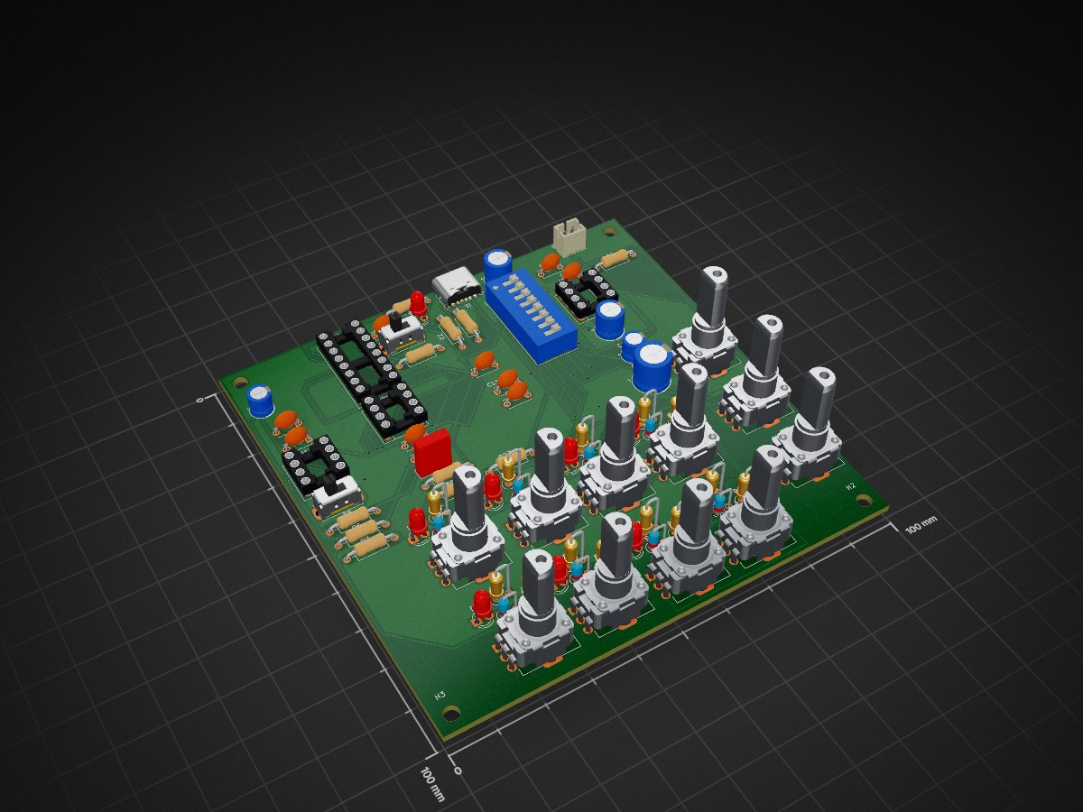
Synthy is a small 8-step synth with no microcontroller and no code. It plays a looping melody of 8 notes, and you set each note by turning its own knob. Everything runs off USB-C.
Synthy is an open-source printed circuit board by kgiorgi, from the kgiorgi/synthy repository on GitHub, published under the MIT licence. It is a 2-layer board of 100 × 100 mm with 84 parts on 70 nets, routed with 734 tracks and 65 vias.
It is built around the LM386, LMC555CN and 74HC4017D. Its parts include 27 resistors, 17 diodes, 16 capacitors, 4 ICs and 3 switches.


Synthy is a small 8-step synth with no microcontroller and no code. It plays a looping melody of 8 notes, and you set each note by turning its own knob. Everything runs off USB-C.
How it works
One 555 timer ticks like a metronome. Every tick moves a 4017 counter on to the next step, so the 8 steps light up one after another and then start over.
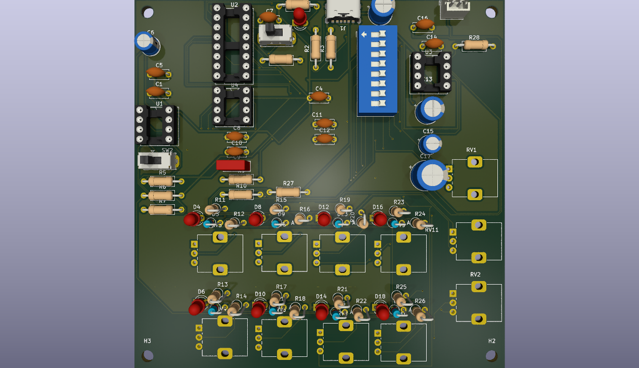
Each step has its own knob, LED and switch. When a step is active, its knob sets how fast a second 555 timer buzzes, and that's the note you hear. The LED shows which step is playing, and the switch can turn a step off so it becomes a rest.
The sound then goes through a tone knob that goes from soft to buzzy, a volume knob, and a small LM386 amplifier that drives a speaker.
How to play it
Plug in USB-C and the loop starts.
Turn the 8 step knobs to change the notes. TEMPO changes the speed. TONE makes the sound softer or buzzier, and VOLUME sets how loud it is.
Flip the small switches by the LEDs to turn steps into rests and make rhythms. The 4/8 switch picks a 4-step or 8-step loop, and RUN/STOP freezes the loop on one note so you can tune it.
Before drawing the board
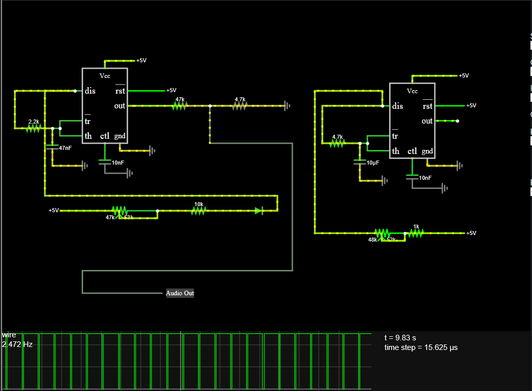
I built both timers in a circuit simulator first to check the numbers. The tone timer covers about 210 Hz to 1.5 kHz, which is roughly three octaves, and the clock goes from about 1.3 to 13 steps per second. Both matched what I calculated, so I didn't need to change any part values. The simulation file is in the sim folder.
Parts
The main parts are two LMC555 timers, a 74HC4017 counter, an LM386 amplifier, 11 knobs, 9 LEDs, 8 diodes, an 8-way DIP switch, two slide switches, a USB-C socket and a small 8 ohm speaker. The full list with LCSC part numbers is in production/BOM.csv.
I bought the knobs myself on AliExpress because LCSC was out of stock. If the LMC555 sells out, two regular NE555s plus a 74HCT4017 work in the same spots.
Testing it after building
The chips go in sockets, so the board can be tested one part at a time.
With no chips in, plug in USB-C. The power LED should light, and every chip socket should have about 5 V. Put in the clock and the counter. The step LEDs should walk from 1 to 8 and repeat, TEMPO should change the speed, and RUN/STOP should freeze it. Put in the tone timer and the amplifier. The speaker should play the loop, each knob should change its own note, and a step with its switch off should be silent.
If something fails, only that one part of the circuit needs checking.
Files
hardware/kicad has the KiCad project. production has the gerbers and the BOM. docs/images has the render and schematic. sim has the simulator file.
What I learned
First of all measuring frequencies in circuits. A little bit niche but at least it wasn't difficult to understand unlike well, copper layers in kicad? I still can't even begin to explain what was happening towards the end but I got the intuition which is sufficient for me.
| Qty | Value | Footprint | References |
|---|---|---|---|
| 9 | B100k | Potentiometer_THT:Potentiometer_Alps_RK09K_Single_Vertical | RV2, RV3, RV4, RV5, RV6, RV7, RV8, RV9, RV10 |
| 9 | LED | LED_THT:LED_D3.0mm | D2, D4, D6, D8, D10, D12, D14, D16, D18 |
| 8 | 10k | Resistor_THT:R_Axial_DIN0207_L6.3mm_D2.5mm_P2.54mm_Vertical | R12, R14, R16, R18, R20, R22, R24, R26 |
| 8 | 1N4148 | Diode_THT:D_DO-35_SOD27_P2.54mm_Vertical_AnodeUp | D5, D7, D9, D11, D13, D15, D17, D19 |
| 8 | 2.2k | Resistor_THT:R_Axial_DIN0207_L6.3mm_D2.5mm_P2.54mm_Vertical | R11, R13, R15, R17, R19, R21, R23, R25 |
| 5 | 100nF | Capacitor_THT:C_Disc_D5.0mm_W2.5mm_P5.00mm | C4, C5, C7, C8, C14 |
| 4 | MountingHole_3.2mm_M3 | MountingHole:MountingHole_3.2mm_M3 | H1, H2, H3, H4 |
| 2 | 100µF | Capacitor_THT:CP_Radial_D6.3mm_P2.50mm | C3, C13 |
| 2 | 10nF | Capacitor_THT:C_Disc_D5.0mm_W2.5mm_P5.00mm | C1, C10 |
| 2 | 10µF | Capacitor_THT:CP_Radial_D5.0mm_P2.00mm | C6, C15 |
| 2 | 1k | Resistor_THT:R_Axial_DIN0207_L6.3mm_D2.5mm_P10.16mm_Horizontal | R4, R6 |
| 2 | 4.7k | Resistor_THT:R_Axial_DIN0207_L6.3mm_D2.5mm_P10.16mm_Horizontal | R7, R27 |
| 2 | 5.1k | Resistor_THT:R_Axial_DIN0207_L6.3mm_D2.5mm_P10.16mm_Horizontal | R2, R3 |
| 2 | LMC555CN | Package_DIP:DIP-8_W7.62mm_Socket | U1, U4 |
| 2 | SW_SPDT | Button_Switch_THT:SW_Slide_SPDT_Straight_CK_OS102011MS2Q | SW2, SW3 |
| 1 | 10 | Resistor_THT:R_Axial_DIN0207_L6.3mm_D2.5mm_P10.16mm_Horizontal | R28 |
| 1 | 100k | Resistor_THT:R_Axial_DIN0207_L6.3mm_D2.5mm_P10.16mm_Horizontal | R8 |
| 1 | 10k | Resistor_THT:R_Axial_DIN0207_L6.3mm_D2.5mm_P10.16mm_Horizontal | R5 |
| 1 | 1µF | Capacitor_THT:C_Disc_D5.0mm_W2.5mm_P5.00mm | C12 |
| 1 | 2.2k | Resistor_THT:R_Axial_DIN0207_L6.3mm_D2.5mm_P10.16mm_Horizontal | R9 |
| 1 | 220µF | Capacitor_THT:CP_Radial_D8.0mm_P3.50mm | C17 |
| 1 | 4.7nF | Capacitor_THT:C_Disc_D5.0mm_W2.5mm_P5.00mm | C11 |
| 1 | 47k | Resistor_THT:R_Axial_DIN0207_L6.3mm_D2.5mm_P10.16mm_Horizontal | R10 |
| 1 | 47nF | Capacitor_THT:C_Rect_L7.2mm_W2.5mm_P5.00mm_FKS2_FKP2_MKS2_MKP2 | C9 |
| 1 | 47nF | Capacitor_THT:C_Disc_D5.0mm_W2.5mm_P5.00mm | C16 |
| 1 | 74HC4017 | Package_DIP:DIP-16_W7.62mm_Socket | U2 |
| 1 | A100k | Potentiometer_THT:Potentiometer_Alps_RK09K_Single_Vertical | RV1 |
| 1 | B50k | Potentiometer_THT:Potentiometer_Alps_RK09K_Single_Vertical | RV11 |
| 1 | Conn_01x02 | Connector_JST:JST_PH_B2B-PH-K_1x02_P2.00mm_Vertical | J2 |
| 1 | LM386 | Package_DIP:DIP-8_W7.62mm_Socket | U3 |
| 1 | SW_DIP_x08 | Button_Switch_THT:SW_DIP_SPSTx08_Slide_9.78x22.5mm_W7.62mm_P2.54mm | SW1 |
| 1 | USB_C_Receptacle_PowerOnly_6P | Connector_USB:USB_C_Receptacle_GCT_USB4125-xx-x-0190_6P_TopMnt_Horizontal | J1 |
It measures 100 × 100 mm and has 2 copper layers, 1.6 mm thick.
84 parts, built around the LM386, LMC555CN and 74HC4017D. The full list of its parts is on this page, with links to each part's symbol and footprint where PCBKit's library has them.
From the kgiorgi/synthy repository on GitHub, at the commit this page was made from: the board is hardware/kicad/synthy/synthy.kicad_pcb and its schematic hardware/kicad/synthy/synthy.kicad_sch. PCBKit opens the board in the browser, with nothing to install.
Its repository publishes it under the MIT licence: you may reuse it on that licence's terms (keep the author's notice, and for a copyleft licence share your changes alike).
ahan-halder/Audio-Power-Amplification-using-Class-D-Topology
Class D Amplifier


sqfmi/BTTF-BADGE
Order PCBs from OSHPARK (Choose After Dark PCBs for Best Results): https://oshpark.com/projects/hdZOu9qd

AlpenglowIndustries/Alpenglow_FoxyPride_PCB
An awesome SMT soldering board with space for writing pronouns, where you can choose your own pride-themed colors for the LEDs.


niwa-yamaguchi/Contact-Monitor-Board
スキャン出力が H になると、その ch の LED 側と MOSFET 側が同時にアクティブになります。 外部接点が閉じていれば電流が流れて LED が点灯し、開いていれば経路が切れて消灯します。 出力が L の間はゲートも L なので MOSFET が OFF になり、その ch は完全に切り離されます。

pschilkdev/QuadCopter_PP
Main Repository for all code for the Quadcopter Project. Personal Project 2015/16 IICS