2 layers108 × 80 mm
Ghost fader
chris-albert/ghost-fader
MIDI-controlled volume and pan for balanced stereo synths (Teensy 4.0 + PGA2310)
82 parts

 kennito2035/convey4
CONVEY: open 8-channel patient-isolated EEG/sEMG/ECG acquisition board (ADS1299, KiCad 10)
Convey is an open-source printed circuit board by kennito2035, from the kennito2035/convey repository on GitHub, published under the CERN-OHL-S-2.0 licence. It is a 4-layer board of 64 × 64 mm with 146 parts on 128 nets, routed with 1,489 tracks and 189 vias.
It is built around the REM1-0512S, TPS7A4901DGN and ADS1299IPAG, with the ICM-42688-P, ISO7761FDW and ISO7762FDW among its other parts. Its parts include 68 capacitors, 45 resistors, 11 ICs, 8 diodes and 5 connectors.


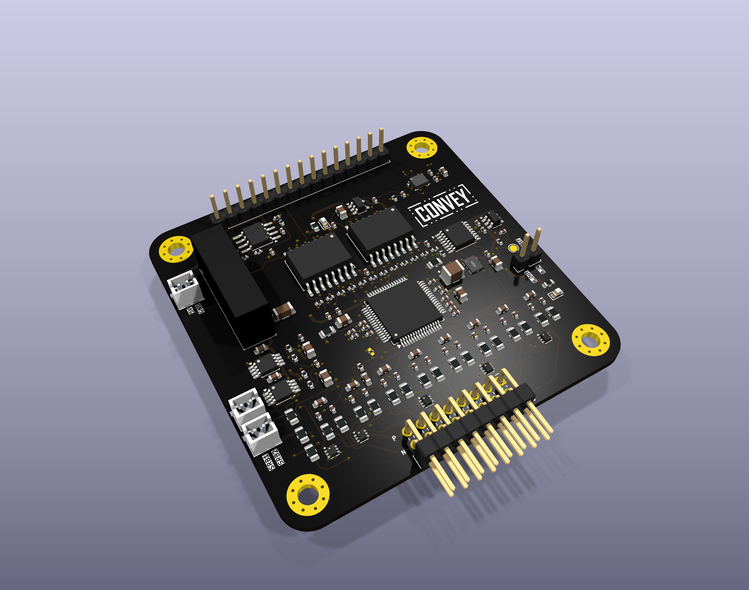
CONVEY is an open-hardware, patient-isolated, general-purpose biosignal front end: eight 24-bit differential channels around the TI ADS1299, on a 64 × 64 mm 4-layer board that records EEG, surface EMG or ECG depending only on configuration and electrode montage. It runs from a 5 V USB power bank, isolates the subject from the host to 5000 V_RMS (reinforced), cancels mains interference in hardware with an active bias drive, and carries a 6-axis IMU clock-locked to the ADC's oscillator so motion and biosignal share one time base. Any microcontroller drives it over a 15-pin SPI header; a reference ESP32-S3 firmware is included.
It exists because an 8-channel OpenBCI Cyton costs ≈ ₱70 000+ (16 channels ≈ ₱140 000+) in the Philippines before shipping, import and electrodes (the store's own peso prices on 23 August 2026 were ₱78,200.00 and ₱156,500.00; a feature-by-feature comparison is in the tech report §2, Table 1). CONVEY is the accessible alternative, and a fully documented instrument, so the acquisition chain itself can be studied as well as used.
The name is the job: to convey is to carry something from one place to another and to communicate what is felt. The body produces its messages as microvolt signals in the brain, heart and muscles; this board carries them across the isolation barrier, cleanly and safely, to where they can be read.
Status : design-verified and fab-ready; not yet fabricated. DRC 0 errors / 0 unconnected · 56/56 automated design gates · isolation barrier verified on the Gerbers · ERC 0 · two ground-up adversarial design reviews with every finding closed · BOM with live-verified LCSC stock. Fabrication + assembly + shipping to the Philippines is 2-3 weeks; the first article is ordered the week after Reverie Hacks 2026. Details:
docs/TECH_REPORT.md§11. All performance figures below are datasheet / design values, not measurements.
Submitted to Reverie Hacks 2026, Embedded Systems track.
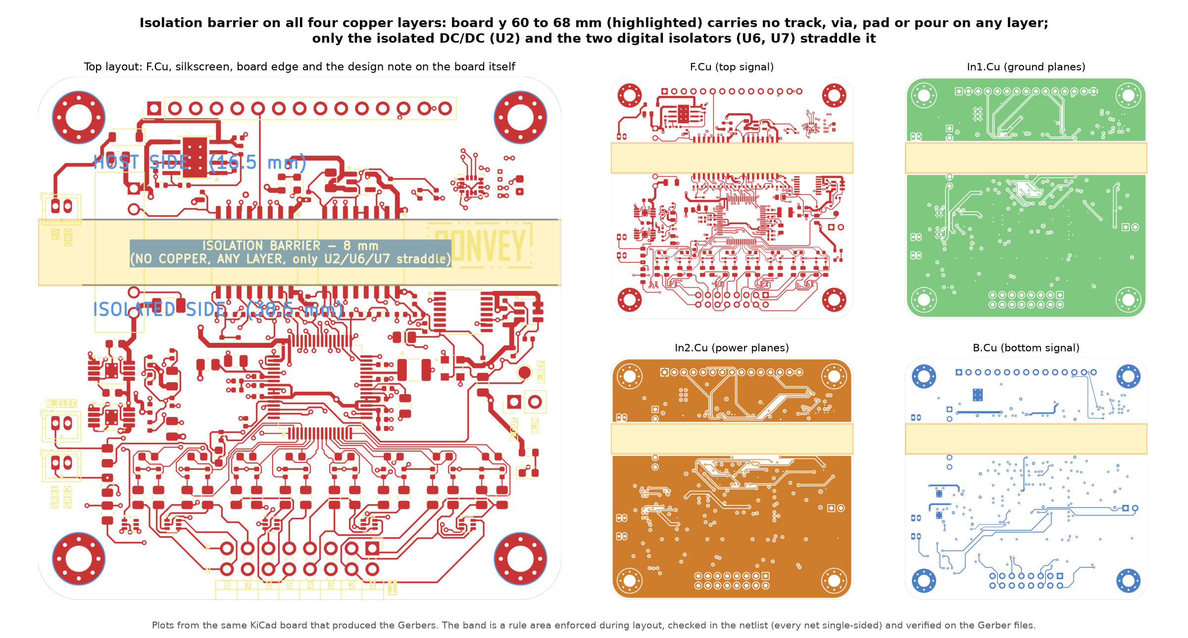
The highlighted band (board y 60 to 68 mm) is a rule area that forbids tracks, vias, pads and pours on every layer. The host side (J1 header, IMU, input protection) sits above it, the patient side (ADS1299, electrodes, reference, clock, regulators) below it, and only the isolated DC/DC converter and the two digital isolators straddle it. The band is checked three times: in the netlist (every net is single-sided), in the KiCad rule area, and on the Gerber files by verify_gerber_barrier.py. The board's own design note on the comments layer marks it; the KiCad editor view is in hardware/images/pcb_layout_editor.png. Why there is no physical board yet, and what stands in for one: docs/TECH_REPORT.md §11.
| Channels | 8 differential, 24-bit ΔΣ (ADS1299), programmable gain 1-24 |
| Sample rate | 250 SPS - 4 kSPS (sEMG default 4000 SPS; −3 dB 1048 Hz) |
| Input-referred noise | 0.65 µV_RMS at gain 12 (datasheet); ≈ 0.53 µV_RMS estimated 20-500 Hz incl. front end |
| Resolution at gain 12 | 44.70 nV/LSB, ±375 mV full scale |
| CMRR | −110 dB (datasheet; 0.1 % matched 5.11 kΩ input resistors) |
| Input protection | TPD4E1B06 TVS on every electrode (±12 kV contact / ±15 kV air), C0G anti-alias network |
| Bias / reference | Active bias drive (right-leg-drive style), SRB1/SRB2 reference routing, lead-off detection |
| Isolation | 8.000 mm creepage barrier with no copper on any of the 4 layers; ISO7761F/ISO7762F reinforced 5000 V_RMS; REM1-0512S medical-grade isolated DC/DC; net-less mounting holes |
| Motion | ICM-42688-P IMU, CLKIN = 2.048 MHz ÷ 64 = 32.000 kHz from the ADC's own oscillator |
| Power | 5 V USB power bank (JST ZH); TPS2596 eFuse OVLO 5.73 V / UVLO 4.17 V / 0.46 A limit + reverse-polarity diode; ultralow-noise TPS7A49 LDOs on the isolated side |
| Host | 15-pin 2.54 mm header: SPI (shared SCLK/MOSI, separate MISO for ADC and IMU), DRDY, RESET, PWDN, START, CLKSEL, IMU INT; 3.3 V logic |
| Board | 64 × 64 mm, 4 layers (signal / GND / power / signal), 146 components, 0.127 mm min trace, 0.6/0.3 mm vias (0.8/0.4 on power), 282 PTH - standard JLCPCB 4-layer + SMT |
| Path | Contents |
|---|---|
hardware/kicad/ | KiCad 10 project: CONVEY.kicad_pro/.kicad_sch/.kicad_pcb, project symbol/footprint libs, vendor STEP models, the two verifiers |
hardware/fab/ | CONVEY_gerbers.zip (the upload), unzipped Gerbers/drills, JLC BOM + CPL, README_ORDERING.md, sourcing notes |
hardware/images/ | Renders, copper-layer plots, schematic block crops, electrode-placement figures, firmware flowchart |
hardware/docs/ | Schematic PDF · schematic spec · canonical net list · acquisition contract · bring-up plan · part selection · design review · datasheets · references |
firmware/ | Reference ESP32-S3 host firmware (ADS1299 + IMU bring-up, streaming) - compiles, untested on hardware - with algorithm flowchart |
software/ | plot_serial.py live plotter (--demo mode runs without hardware) |
docs/ | Tech report (PDF), JLCPCB quote |
hardware/kicad/CONVEY.kicad_pro. Project libraries resolve through ${KIPRJMOD}; stock symbols/footprints/3D models come from the KiCad installation.From hardware/kicad/, using KiCad's Python (Windows path shown; adjust for your OS):
"C:/Program Files/KiCad/10.0/bin/python.exe" verify_board.py --drc→ 56 checks (geometry, 8 mm barrier on all layers, netlist↔board, footprint/3D resolution, track-width convention, net classes, DRC wrapper), expect 56 passed, 0 failed, 0 errors, unconnected items: 0.
"C:/Program Files/KiCad/10.0/bin/python.exe" verify_gerber_barrier.py→ parses the actual Gerber/Excellon files in hardware/fab/gerbers/ and proves no copper, pour or hole lies in the barrier band on any layer, expect BARRIER ON THE PLOTS: CLEAN.
hardware/fab/README_ORDERING.md: JLCPCB 4-layer, 64 × 64 mm, 1.6 mm, ENIG recommended; upload CONVEY_gerbers.zip, CONVEY_bom_jlcpcb.csv, CONVEY_cpl_jlcpcb_top.csv. Six lines are external-source parts (listed there). Then follow hardware/docs/10_bringup_plan.md, every step has an expected value.
firmware/README.md: ESP32-S3 (Arduino-ESP32 3.3), wiring table for J1, the bring-up sequence (power-up → reset → ID 0x1E → CONFIG1/2/3 → CHnSET → START → RDATAC), DRDY-driven 27-byte frames, IMU on the 32 kHz CLKIN, CSV/binary serial output. It compiles; it has not run on hardware because the hardware does not exist yet. Flowchart: firmware/docs/FLOWCHART.md.
Third-party datasheets (listed with SHA-256 in hardware/docs/DATASHEETS.md), vendored reference projects (linked in REFERENCES.md), KiCad stock libraries, the design's working snapshots and backups, and internal working notes.
Hardware: CERN-OHL-S v2 (LICENSE). Firmware, software and scripts: MIT (LICENSE-MIT). See LICENSING.md. CONVEY is a research/educational design, not a medical device.
| Qty | Value | Footprint | References |
|---|---|---|---|
| 20 | 100n | Capacitor_SMD:C_0402_1005Metric | C1, C2, C3, C4, C5, C10, C12, C14, C18, C45, C49, C55, C57, C58, C59, C60 +4 |
| 19 | 5.11k | Resistor_SMD:R_0805_2012Metric | R1, R2, R3, R4, R5, R6, R10, R11, R12, R13, R14, R15, R16, R18, R19, R20 +3 |
| 16 | 560p | Capacitor_SMD:C_0402_1005Metric | C29, C30, C31, C32, C33, C34, C35, C36, C37, C38, C39, C40, C41, C42, C43, C44 |
| 12 | 10k | Resistor_SMD:R_0402_1005Metric | R21, R22, R23, R24, R25, R44, R45, R46, R47, R48, R49, R57 |
| 8 | 10n | Capacitor_SMD:C_0603_1608Metric | C21, C22, C23, C24, C25, C26, C27, C28 |
| 7 | 10u | Capacitor_SMD:C_0805_2012Metric | C6, C9, C11, C13, C46, C50, C66 |
| 5 | 10n | Capacitor_SMD:C_0402_1005Metric | C52, C53, C56, C63, C67 |
| 5 | TPD4E1B06 | Package_TO_SOT_SMD:SOT-563 | D1, D2, D3, D4, D5 |
| 4 | 1u | Capacitor_SMD:C_0402_1005Metric | C16, C17, C19, C47 |
| 4 | MountingHole_M3 | MountingHole:MountingHole_3.2mm_M3_Pad_Via | H1, H2, H3, H4 |
| 3 | 100k | Resistor_SMD:R_0402_1005Metric | R51, R54, R56 |
| 2 | 1u_25V | Capacitor_SMD:C_0603_1608Metric | C64, C65 |
| 2 | TPS7A4901 | CONVEY:TPS7A4901_HVSSOP-8-1EP_3x3mm_P0.65mm_ThermalVias | U3, U4 |
| 1 | 0R | Resistor_SMD:R_0805_2012Metric | FB1 |
| 1 | 0R_star | Resistor_SMD:R_0805_2012Metric | NB1 |
| 1 | 1.5k | Resistor_SMD:R_0603_1608Metric | R58 |
| 1 | 100 | Resistor_SMD:R_0402_1005Metric | R50 |
| 1 | 100p | Capacitor_SMD:C_0402_1005Metric | C54 |
| 1 | 100u_TANT | Capacitor_SMD:C_1210_3225Metric | C15 |
| 1 | 10u | Capacitor_SMD:C_1206_3216Metric | C48 |
| 1 | 15k | Resistor_SMD:R_0402_1005Metric | R62 |
| 1 | 178k | Resistor_SMD:R_0402_1005Metric | R55 |
| 1 | 1M | Resistor_SMD:R_0402_1005Metric | R17 |
| 1 | 1k | Resistor_SMD:R_0402_1005Metric | R52 |
| 1 | 1n | Capacitor_SMD:C_0603_1608Metric | C20 |
| 1 | 22p | Capacitor_SMD:C_0402_1005Metric | C51 |
| 1 | 2k | Resistor_SMD:R_0402_1005Metric | R63 |
| 1 | 2u2 | Capacitor_SMD:C_0603_1608Metric | C62 |
| 1 | 324k | Resistor_SMD:R_0402_1005Metric | R53 |
| 1 | 330 | Resistor_SMD:R_0603_1608Metric | R59 |
| 1 | 5.6k | Resistor_SMD:R_0402_1005Metric | R61 |
| 1 | 51k | Resistor_SMD:R_0402_1005Metric | R60 |
| 1 | ADS1299IPAG | Package_QFP:TQFP-64_10x10mm_P0.5mm | U1 |
| 1 | ASEM1-2.048MHZ | CONVEY:ASEM1-2.048MHZ_3.2x2.5mm | Y1 |
| 1 | BIAS_LOOP | Connector_PinHeader_2.54mm:PinHeader_1x02_P2.54mm_Vertical | JP2 |
| 1 | BLUE | LED_SMD:LED_0603_1608Metric | D8 |
| 1 | ELECTRODES | Connector_PinHeader_2.54mm:PinHeader_2x08_P2.54mm_Horizontal | J2 |
| 1 | ICM-42688-P | CONVEY:ICM-42688-P_LGA-14_3x2.5mm_P0.5mm | U8 |
| 1 | ISO7761FDW | CONVEY:SOIC-16W_7.5x10.3mm_P1.27mm_8mmCreepage | U6 |
| 1 | ISO7762FDW | CONVEY:SOIC-16W_7.5x10.3mm_P1.27mm_8mmCreepage | U7 |
| 1 | JST_ZH_BIAS | CONVEY:JST_ZH_B2B-ZR_1x02_P1.50mm_Vertical | J3 |
| 1 | JST_ZH_SRB | CONVEY:JST_ZH_B2B-ZR_1x02_P1.50mm_Vertical | J4 |
| 1 | MCU_HDR | Connector_PinHeader_2.54mm:PinHeader_1x15_P2.54mm_Vertical | J1 |
| 1 | PWR_IN | CONVEY:JST_ZH_B2B-ZR_1x02_P1.50mm_Vertical | J5 |
| 1 | RED | LED_SMD:LED_0603_1608Metric | D7 |
| 1 | REM1-0512S | CONVEY:REM1-0512S_SIP7 | U2 |
| 1 | SN74HC4040 | Package_SO:TSSOP-16_4.4x5mm_P0.65mm | U5 |
| 1 | TLV70233 | Package_TO_SOT_SMD:SOT-23-5 | U9 |
| 1 | TPS259631DDAR | Package_SO:Texas_HTSOP-8-1EP_3.9x4.9mm_P1.27mm_EP2.95x4.9mm_Mask2.4x3.1mm_ThermalVias | U11 |
| 1 | TPS3808G30 | Package_TO_SOT_SMD:SOT-23-6 | U10 |
| 1 | TP_BIASREF | TestPoint:TestPoint_Pad_D1.5mm | TP4 |
| 1 | reverse-prot | Diode_SMD:D_SOD-123 | D6 |
It measures 64 × 64 mm and has 4 copper layers, 1.6 mm thick.
146 parts, built around the REM1-0512S, TPS7A4901DGN, ADS1299IPAG and ICM-42688-P. The full list of its parts is on this page, with links to each part's symbol and footprint where PCBKit's library has them.
From the kennito2035/convey repository on GitHub, at the commit this page was made from: the board is hardware/kicad/CONVEY.kicad_pcb and its schematic hardware/kicad/CONVEY.kicad_sch. PCBKit opens the board in the browser, with nothing to install.
Its repository publishes it under the CERN-OHL-S-2.0 licence: you may reuse it on that licence's terms (keep the author's notice, and for a copyleft licence share your changes alike).
chris-albert/ghost-fader
MIDI-controlled volume and pan for balanced stereo synths (Teensy 4.0 + PGA2310)

wafaffles/Miniamp
A pocketable DAC/amp based on the PCM2706CPJTR IC. It will be a low power DAC/amp with multiple buttons to be able to easily control media without opening the device.

Tinkerbug-Robotics/TinkerRocket
Model rocket flight computer, ground station, iOS app, and simulation


azerimaker/BMS_3-5S
3-5S Battery Management System based on TI bq76920 IC and MSP430 uC.

M0LTE/pi-transceiver
An attempt to build a complete ham radio transceiver around a Raspberry Pi

