4 layers56 × 60 mm
PCBA KNOT
intechstudio/knot
Knot is the bridge between old-school MIDI gear like synthesizers, groove boxes, guitar pedals and neat USB MIDI devices.
111 parts58GPL-3.0

 kd4cbm/EngModem-Mini
Retro dial-up-modem-styled ESP32-S3 board (RS-232, VFD status display, SD, LEDs) running Zimodem-VFD. KiCad hardware + qualified firmware; Rev5 built and bench-qualified.
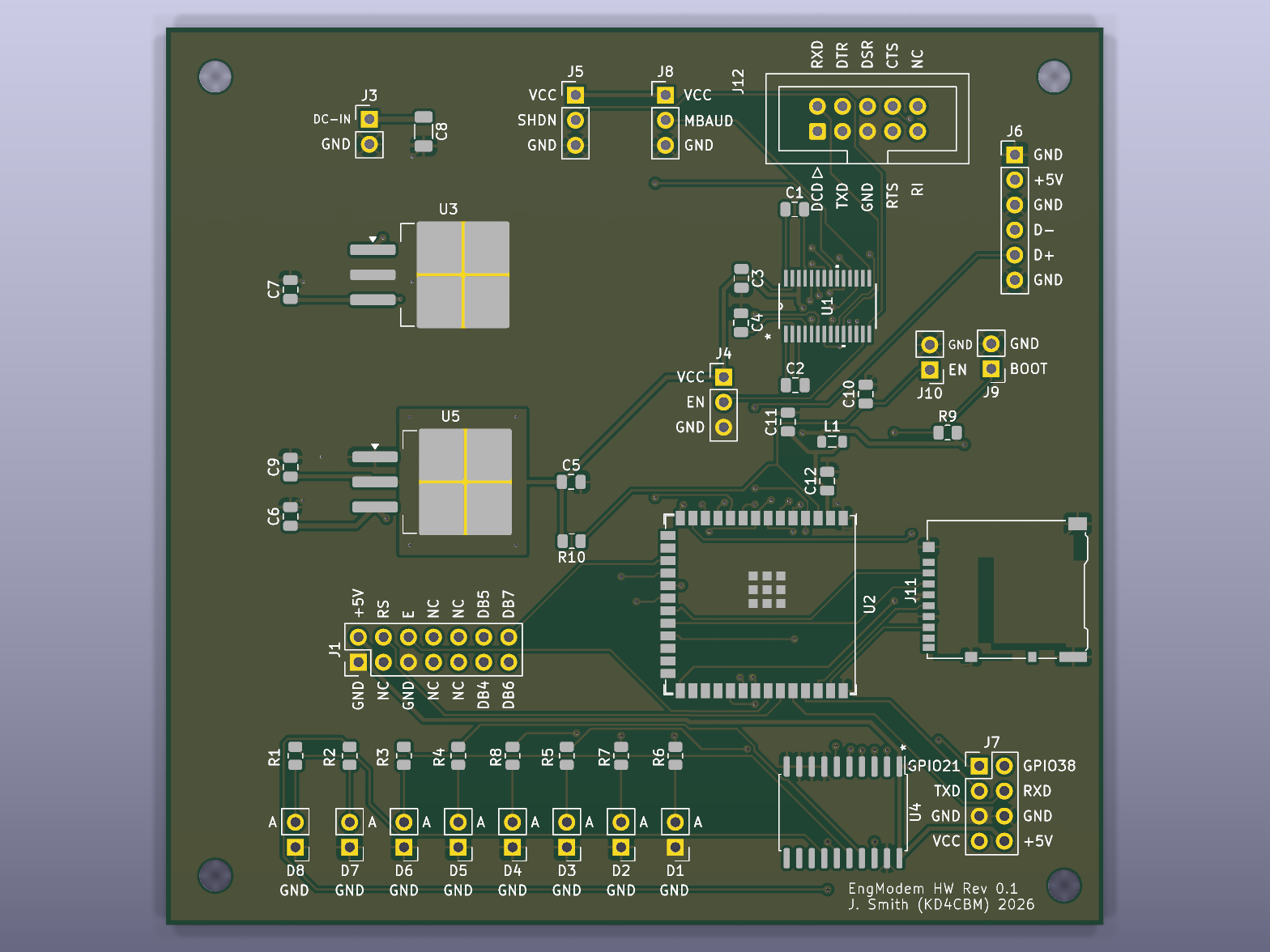
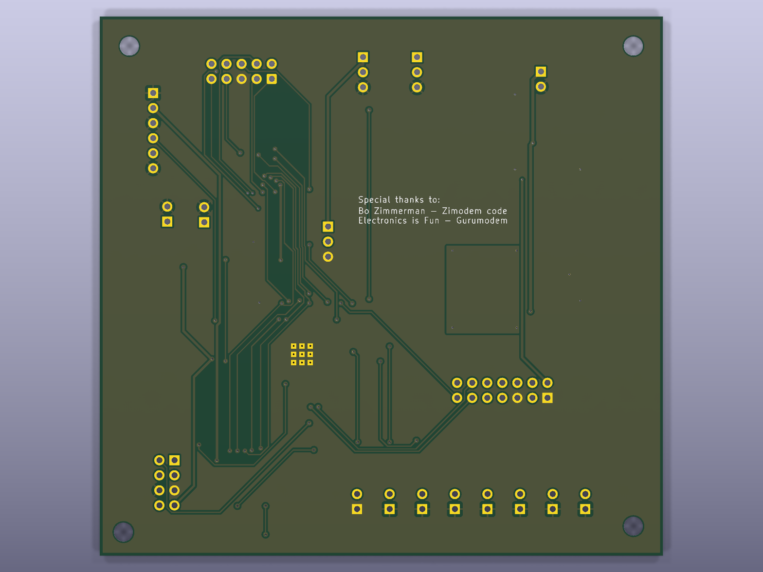
EngModem Modular Routed Rev5 is an open-source printed circuit board by kd4cbm, from the kd4cbm/EngModem-Mini repository on GitHub, published under the CERN-OHL-S-2.0 licence. It is a 2-layer board of 95 × 91 mm with 51 parts on 84 nets, routed with 657 tracks and 80 vias.
It is built around the 74HCT245, ESP32-S3-WROOM-1U-N4 and LM7805S2/TR. Its parts include 12 capacitors, 11 connectors, 10 resistors, 8 diodes and 5 ICs. It belongs with the lEDs and displays and retro computing and games boards and the ESP32 boards of this library.


A retro dial-up-modem-styled ESP32-S3 board: RS-232 (true DCE levels via
MAX3237), a 24x2 character VFD status display, a microSD card slot, 8
status LEDs, and USB-C, built around the ESP32-S3-WROOM-1U module. Runs
Zimodem - Bo Zimmerman's Hayes
AT-command modem emulator/internet gateway - via the
Zimodem-VFD fork, which adds the
VFD status display this board uses. The firmware qualified on this exact
hardware, further specialised for it, is included in firmware/.
One Rev5 board has been built, brought up and bench-qualified with the firmware
in firmware/ (revision firmware-v7-rev1), September 2026:
programming over USB, boot and debug UART, WiFi, microSD, the VFD, the status
LEDs, RS-232 at every rate from 300 to 921600 baud, RTS/CTS flow control, DTR,
DCD and RI, and byte-exact data integrity through TCP connections. The full
results - and, just as importantly, what was not tested (no rail-voltage or
signal-level measurements, single unit, no long soak, no ESD/EMC) - are in
docs/QUALIFICATION.md.
Bring-up turned up a few things worth knowing before you build one:
docs/J12_CABLE_GUIDE.md.docs/BRING_UP.md.docs/ERRATA.md.docs/ERRATA.md.
Also check the LED order at assembly (two LEDs were swapped on the tested unit).docs/ERRATA.md and
docs/QUALIFICATION.md.docs/ERRATA.md.This is a functional qualification of a single unit, not a compliance test. Expect further revisions.
This board exists to run Bo Zimmerman's Zimodem - the Hayes AT-command modem emulator this whole project is built around. None of this would have a reason to exist without that project. Thank you, Bo.
Design checks - every revision was checked with KiCad's own tools before being carried forward:
docs/ERRATA.md.Hardware qualification - a real Rev5 board, tested on the bench with the
included firmware: docs/QUALIFICATION.md.
This project uses two public third-party KiCad libraries that aren't bundled here - install both via KiCad's Plugin and Content Manager before opening the project:
com_github_espressif_kicad-libraries) -
ESP32-S3-WROOM-1U symbol/footprintThe project's one genuinely custom dependency, a small RetroWiFiModem
library providing the SOIC-20W bus-transceiver symbol/footprint used at U4
(both the original 74HCT245 and the CD74HCT640M it was replaced with share
the symbol's underlying pinout), is bundled under
hardware/kicad/libraries/ and wired up via
the project-local sym-lib-table/fp-lib-table, so it
resolves automatically - no separate install needed for that one.
DCE pinout in the AT/Everex header order (header pin n = DE-9 pin n) -
wire straight-through to a DTE (PC/terminal). Many ready-made header-to-DE-9
cables use a different (DTK/Intel) order and will not work - read
docs/J12_CABLE_GUIDE.md:
| Pin | 1 | 2 | 3 | 4 | 5 | 6 | 7 | 8 | 9 |
|---|---|---|---|---|---|---|---|---|---|
| Signal | DCD | RXD | TXD | DTR | GND | DSR | RTS | CTS | RI |
Full connector/power-regulation detail (including the U3/U5 substitution
below) is in PIN_MAP.md; a running changelog is in
CHANGES.md.
firmware/ - the qualified firmware: source, prebuilt
binaries with checksums, and the hardware QA test scripts (start with its
README)docs/ - BRING_UP.md (builder's guide:
jumpers, first power, flashing, troubleshooting),
QUALIFICATION.md (test report),
ERRATA.md (known issues),
J12_CABLE_GUIDE.md (cabling)hardware/kicad/ - full KiCad 10 project (schematic
hardware/kicad/libraries/ - bundled
custom library (see Prerequisite libraries)enclosure/ - Hammond 1455U2201BK panel drill/router jigs
(front: VFD window, LEDs, mounting holes; rear: DB9, USB-C, power
jack/switch, boot/reset, external antenna) - see its own
README for the preliminary-hardware disclaimer
and usage instructionsmanufacturing/Gerbers_EngModem-Mini_Rev5.zip -
Gerber + Excellon drill files, ready to upload to a fabmanufacturing/BOM_PCBA_JLCPCB.csv -
bill of materials for the SMD parts JLCPCB will assemble, with LCSC part
numbers verified against LCSC's own listings where a specific
manufacturer part is called for. Common passives (resistors, most
capacitors) intentionally list full specs with no pinned LCSC number -
JLCPCB's basic-parts catalog is a live, dynamic search that isn't
reliably scriptable, and these are common enough values that matching
one at checkout takes seconds. U3, U4 and U5 are intentionally excluded
manufacturing/BOM_full.csv - every part
on the board, including the through-hole connectors, headers, LED
positions, and U3/U5, for your own hand-assembly shopping listmanufacturing/CPL_SMD.csv - placement
(component position) file for the JLCPCB-assembled SMD parts, in
JLCPCB's expected column format (Designator, Mid X, Mid Y, Layer, Rotation), generated directly from the PCB's real component
coordinates. U3, U4 and U5 excluded, same as the PCBA BOM.Gerbers + BOM_PCBA_JLCPCB + CPL_SMD together are what JLCPCB's PCBA (assembly) order flow asks for. Before ordering, check every SMD part's orientation and position in JLCPCB's assembly preview tool - their preview renders whichever specific LCSC library part it matched to each BOM row, using that part's own reference point, which doesn't always agree with KiCad's footprint origin (for angle or position). Their preview UI lets you nudge/rotate a part and save the correction directly, no file regeneration needed - do that check first, especially for U1 (MAX3237EIPWR) and U2 (the ESP32 module).
JLCPCB's placement preview surfaced a real footprint mismatch on both
regulators: the originally spec'd parts (HGSEMI LM7805S2/TR for U3, ST
LD1086D2T33TR for U5) don't reliably match this board's 3-lead D2PAK/
TO-263-3 footprint - LCSC's own listings show both as 2-lead packages
(and JLCPCB's 3D model for U3 shows "TO263-5" case marking), while ST's
LD1086 datasheet itself defines two different D²PAK mechanical variants
under one ambiguous order code. Rather than risk a bad PCBA placement,
both are DNP for JLCPCB assembly - BOM_full.csv lists verified
replacement parts to hand-solder instead, sourced from Mouser/DigiKey:
Unlike U3/U5, this wasn't a footprint mismatch - the schematic's generic 74HCT245 (non-inverting)
placed and worked fine, but reads five front-panel LEDs inverted (see
docs/ERRATA.md). The fix is a
pin/package-compatible inverting part, TI CD74HCT640M (SOIC-20-300mil, same footprint) - hand-swapped
on the qualified unit and verified correct (2026-09-29; a pad was pulled during desoldering and needed a
trace/pad-level repair, worth planning for). LCSC C1548168 - 0 units in LCSC's own direct stock at
last check, ~3,000 available through LCSC's Other Suppliers channel at a 9-18 business day lead time
(checked 2026-09-29, re-verify before ordering) - excluded here pending confirmed assembly-line stock.
Must be the HCT variant, not HC (HC doesn't meet the 3.3V input threshold at 5V).
| Rev | Notes |
|---|---|
| 0-1 | Original modular layout and placement baseline |
| 2 | SD card socket swapped from a pin header to the real microSD socket (Hirose DM3AT-SF-PEJM5); full reroute |
| 3 | Second SD placement experiment; full reroute; 69 net-derived pin-function silkscreen labels added across every header/LED footprint |
| 4 | Dedicated 0.5mm net class for /DC-IN; solid (non-thermal-relief) zone connections on regulator/shield GND tabs; local /VCC copper pour + thermal vias around U5; ESP32 power-filter components (L1/C11/C12) relocated for shorter real routed-copper paths to U2 |
| 5 | Current - via stitching added under U2's ground-pad cluster (9 vias, exposed copper + matching pads mirrored onto the bottom layer) for bottom-side hand-soldering access; keepout zone added around that cluster, full rip/reroute; U3/U5 excluded from PCBA per the footprint mismatch below |
Hardware design files (schematic, PCB) are released under CERN-OHL-S v2 - a strongly-reciprocal open hardware license: modifications to these design files must be released under the same license if you distribute hardware built from them. See LICENSE.
| Qty | Value | Footprint | References |
|---|---|---|---|
| 8 | LED | Connector_PinHeader_2.54mm:PinHeader_1x02_P2.54mm_Vertical | D1, D2, D3, D4, D5, D6, D7, D8 |
| 5 | 750R | Resistor_SMD:R_0805_2012Metric | R1, R2, R3, R4, R5 |
| 4 | 0.22uf | Capacitor_SMD:C_0805_2012Metric | C1, C2, C3, C4 |
| 4 | MountingHole_3.2mm_M3 | MountingHole_3.2mm_M3 | MH1_TL, MH2_TR, MH3_BL, MH4_BR |
| 3 | 330R | Resistor_SMD:R_0805_2012Metric | R6, R7, R8 |
| 2 | 1uF | Capacitor_SMD:C_0805_2012Metric | C10, C12 |
| 1 | 0.1uF | Capacitor_SMD:C_0805_2012Metric | C7 |
| 1 | 0.1uf | Capacitor_SMD:C_0805_2012Metric | C5 |
| 1 | 0.33uF | Capacitor_SMD:C_0805_2012Metric | C6 |
| 1 | 10K | Resistor_SMD:R_0805_2012Metric | R9 |
| 1 | 10k | Resistor_SMD:R_0805_2012Metric | R10 |
| 1 | 10uF | Capacitor_SMD:C_1206_3216Metric | C8 |
| 1 | 10uF | Capacitor_SMD:C_0805_2012Metric | C11 |
| 1 | 10uf | Capacitor_SMD:C_0805_2012Metric | C9 |
| 1 | 74HCT245 | RetroWiFiModem:SOIC-20W_7.5x12.8mm_P1.27mm | U4 |
| 1 | DB9 | Connector_IDC:IDC-Header_2x05_P2.54mm_Vertical | J12 |
| 1 | DC_PWR_HEADER | Connector_PinHeader_2.54mm:PinHeader_1x02_P2.54mm_Vertical | J3 |
| 1 | DFE201210U-2R2M=P2 (2.2uH, 1.2A, 228mR) | Inductor_SMD:L_0805_2012Metric | L1 |
| 1 | ESP-BOOT | Connector_PinHeader_2.54mm:PinHeader_1x02_P2.54mm_Vertical | J9 |
| 1 | ESP-ENABLE | Connector_PinHeader_2.54mm:PinHeader_1x02_P2.54mm_Vertical | J10 |
| 1 | ESP32-S3-WROOM-1U | PCM_Espressif:ESP32-S3-WROOM-1U | U2 |
| 1 | EXP | Connector_PinHeader_2.54mm:PinHeader_2x04_P2.54mm_Vertical | J7 |
| 1 | LD1086D2T33TR | Package_TO_SOT_SMD:TO-263-3_TabPin2 | U5 |
| 1 | LM7805S2/TR | Package_TO_SOT_SMD:TO-263-3_TabPin2 | U3 |
| 1 | MAX-ENCFG | Connector_PinHeader_2.54mm:PinHeader_1x03_P2.54mm_Vertical | J4 |
| 1 | MAX-MBAUD | Connector_PinHeader_2.54mm:PinHeader_1x03_P2.54mm_Vertical | J8 |
| 1 | MAX-SHDN | Connector_PinHeader_2.54mm:PinHeader_1x03_P2.54mm_Vertical | J5 |
| 1 | MAX3237EIPWR | MAX3237:PW28 | U1 |
| 1 | Micro_SD_Card | Connector_Card:microSD_HC_Hirose_DM3AT-SF-PEJM5 | J11 |
| 1 | USB | Connector_PinHeader_2.54mm:PinHeader_1x06_P2.54mm_Vertical | J6 |
| 1 | VFD | Connector_PinHeader_2.54mm:PinHeader_2x07_P2.54mm_Vertical | J1 |
It measures 95 × 91 mm and has 2 copper layers, 1.6 mm thick.
51 parts, built around the 74HCT245, ESP32-S3-WROOM-1U-N4 and LM7805S2/TR. The full list of its parts is on this page, with links to each part's symbol and footprint where PCBKit's library has them.
From the kd4cbm/EngModem-Mini repository on GitHub, at the commit this page was made from: the board is hardware/kicad/EngModem_Modular_Routed_Rev5.kicad_pcb and its schematic hardware/kicad/EngModem_Modular_Routed_Rev5.kicad_sch. PCBKit opens the board in the browser, with nothing to install.
Its repository publishes it under the CERN-OHL-S-2.0 licence: you may reuse it on that licence's terms (keep the author's notice, and for a copyleft licence share your changes alike).
intechstudio/knot
Knot is the bridge between old-school MIDI gear like synthesizers, groove boxes, guitar pedals and neat USB MIDI devices.


unknownusername504/WirelessMouse
A wireless mouse with open source pcb/schematic as well as drivers to come.


JunOllyLi/TX_PCB
NOTE: the latest PCB had been manufactured was v2.0. But it had the Gimbal ZH-connector reversed. The schematics and PCB drawing had been updated to v2.1 to fix that. But v2.1 had not been really manufactured yet.


mcapdeville/esp32s3aprs
ESP32s3 APRS beacon/tracker/logger, USB kiss TNC , USB audio FM tranceiver with Micropython shell
