2 layers74.9 × 20.3 mm
Rt soldering iron
kcuzner/rt-soldering-iron
Soldering iron driver board for Weller RT tips. A work in progress. Firmware in rust.
126 parts6

 kcuzner/led-watch98
A miniature ARM-powered LED wristwatch
Simple led watch is an open-source printed circuit board by kcuzner, from the kcuzner/led-watch repository on GitHub, published under the MIT licence. It is a 4-layer board of 16.5 × 10.9 mm with 183 parts on 90 nets, routed with 1,625 tracks and 116 vias.
It is built around the TPS62736RGY, 74HC154D and MMA8652FCR1, with the USBLC6-2P6, LTST-C190KRKT and MMBT3904 among its other parts. Its parts include 77 diodes, 25 capacitors, 25 resistors, 6 ICs and 4 switches. It belongs with the wearables boards and the STM32 boards of this library.


By Kevin Cuzner
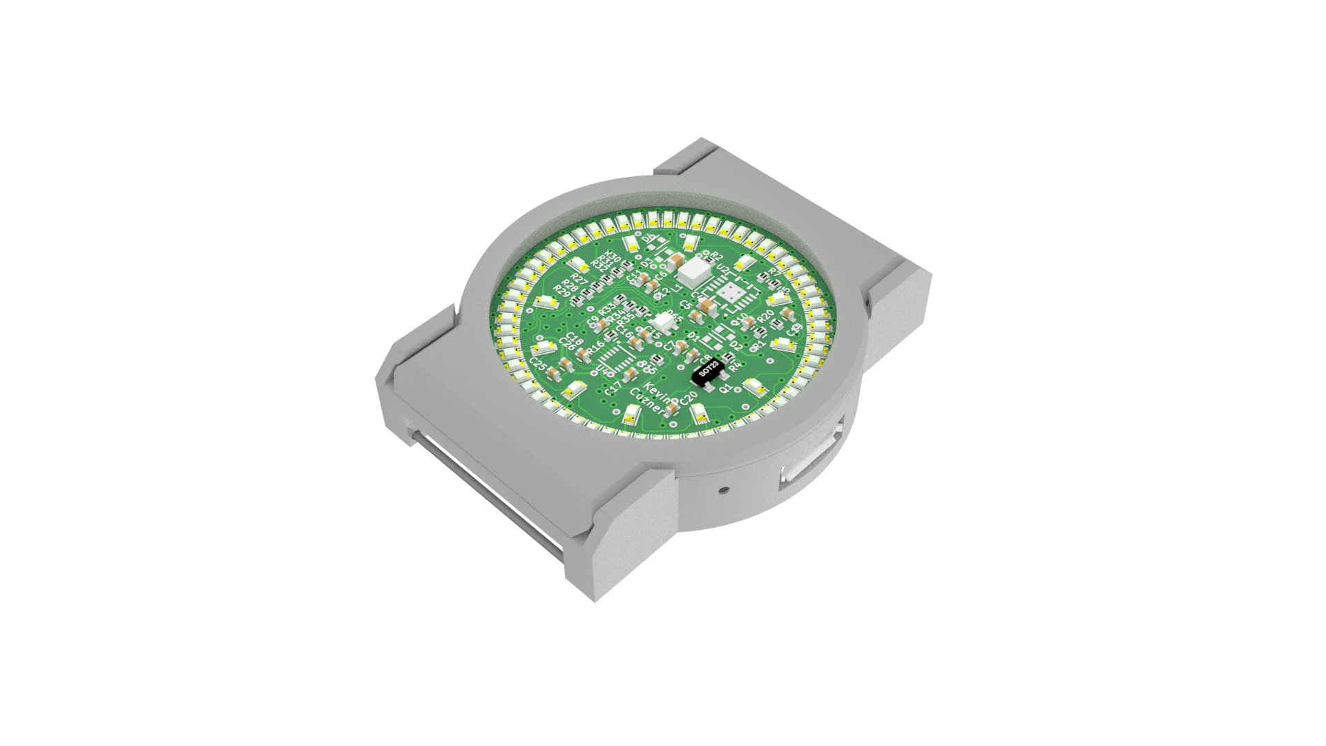
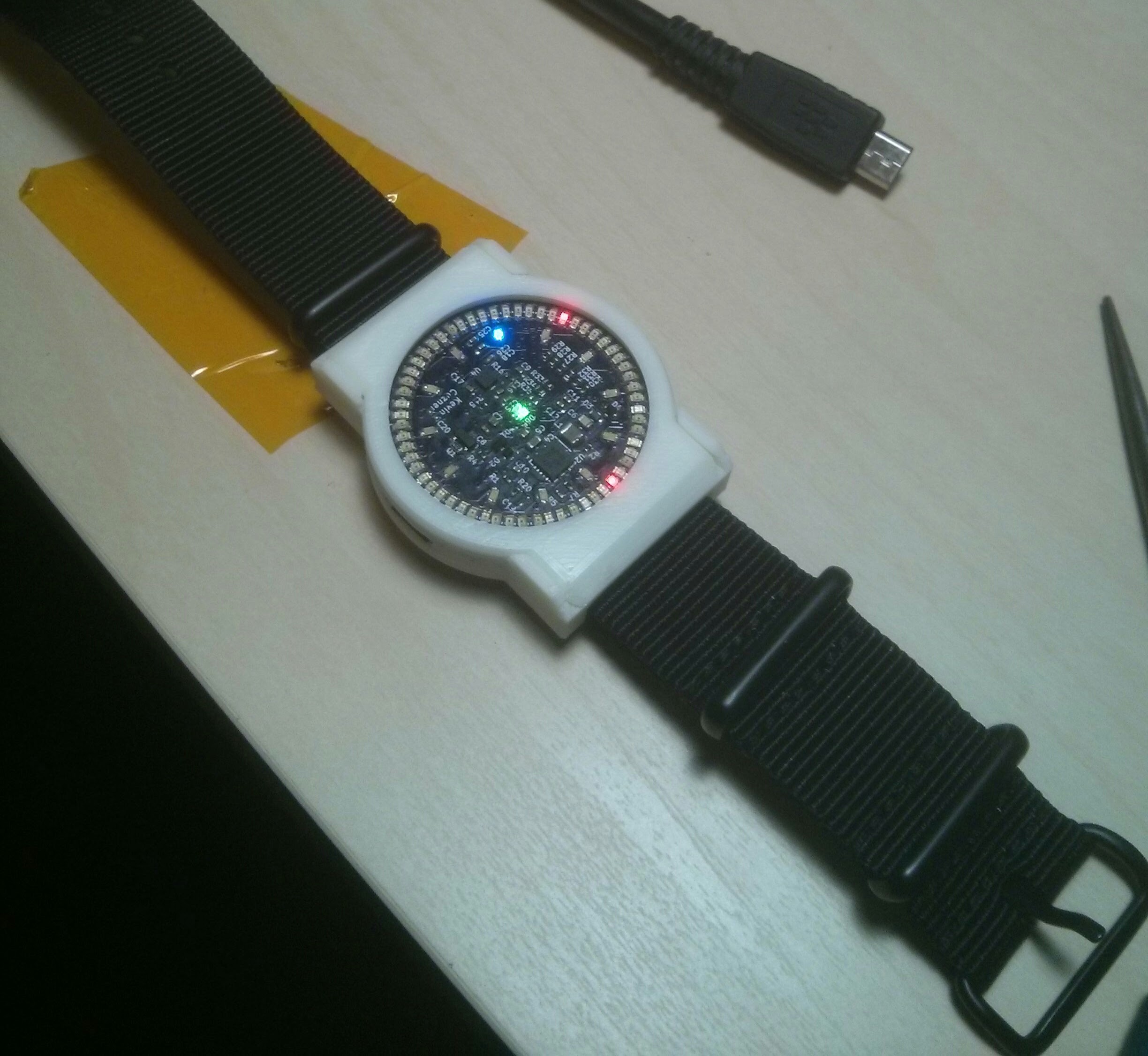
This project is fairly complete, though the bootloader is still a work in progress and may never be completed. The board was built and everything worked after adding some reworks:
There were also two part issues which were resolved in software mostly:
Currently, the only method of input is either through USB or through the accelerometer. The time is set through USB to the current time on the host PC. The watch will automatically sleep when it is removed from USB power and will wake when the accelerometer is tapped. When the watch is awake, the current time is displayed. It currently stays on for about 15 seconds until shutting off again. When USB power is reapplied the watch will reawaken. The future plans are to also enable USB programmability of the watch, though this may never be completed depending on my schedule and level of interest. The buttons may never be used because they are so easy to break, but the idea was to have it behave like a real digital watch with a timer and everything. All it does with the buttons right now is beep when they are pressed.
As this is my first complete hardware design that I am releasing like this, I do reserve the right to take it down at any time. I'm releasing it in the hopes that someone finds it useful, though it clearly has its own problems and shouldn't be considered as a reference design.
| Qty | Value | Footprint | References |
|---|---|---|---|
| 60 | LTST-C190KRKT | LEDs:LED_0603 | D10, D11, D12, D13, D14, D15, D16, D17, D18, D19, D20, D21, D22, D23, D24, D25 +44 |
| 12 | BLUE | LEDs:LED_0603 | D66, D67, D68, D69, D70, D71, D72, D73, D74, D75, D76, D77 |
| 9 | 0.1u | Capacitors_SMD:C_0402 | C2, C8, C9, C10, C12, C16, C17, C18, C26 |
| 8 | 0 | Resistors_SMD:R_0402 | R2, R10, R11, R13, R20, R22, R24, R26 |
| 6 | 150 | Resistors_SMD:R_0402 | R27, R28, R29, R30, R31, R33 |
| 4 | C | Capacitors_SMD:C_0402 | C19, C20, C21, C22 |
| 4 | SPST-4PIN | simple-led-watch:PAN-EVPAV | SW1, SW2, SW3, SW4 |
| 3 | 1u | Capacitors_SMD:C_0402 | C11, C15, C25 |
| 3 | 4.7u | Capacitors_SMD:C_0402 | C1, C3, C5 |
| 2 | 1K | Resistors_SMD:R_0402 | R4, R18 |
| 2 | 22u | Capacitors_SMD:C_0603 | C4, C6 |
| 2 | 4.7K | Resistors_SMD:R_0402 | R15, R16 |
| 2 | 68 | Resistors_SMD:R_0402 | R34, R35 |
| 2 | 8.2p | Capacitors_SMD:C_0402 | C13, C14 |
| 2 | MMBT3904 | TO_SOT_Packages_SMD:SOT-23 | Q1, Q2 |
| 2 | RB521S30T5G | Diodes_SMD:SOD-523 | D2, D4 |
| 1 | 10u | Capacitors_SMD:C_0402 | C7 |
| 1 | 10u | simple-led-watch:SMD_1008 | L1 |
| 1 | 20K | Resistors_SMD:R_0402 | R1 |
| 1 | 3.6V | Diodes_SMD:SOD-523 | D3 |
| 1 | 32.767KHz | simple-led-watch:Crystal-Abracon-ABS07 | Y1 |
| 1 | 47 | Resistors_SMD:R_0402 | R32 |
| 1 | 475K | Resistors_SMD:R_0402 | R7 |
| 1 | 74HC154 | simple-led-watch:DHVQFN24 | U6 |
| 1 | 825K | Resistors_SMD:R_0402 | R5 |
| 1 | ANY | Resistors_SMD:R_0402 | R36 |
| 1 | ANY | Capacitors_SMD:C_0402 | C27 |
| 1 | APTF1616LSEEZGKQBKC | simple-led-watch:LED-0606 | D65 |
| 1 | BATTERY | simple-led-watch:JST-ACH-2PIN | P1 |
| 1 | CDSU101A | Diodes_SMD:SOD-523 | D1 |
| 1 | CSS-0575A-SMT | simple-led-watch:CSS-0575A-SMT | SP1 |
| 1 | MCP73832 | TO_SOT_Packages_SMD:SOT-23-5 | U1 |
| 1 | MMA8652FC | simple-led-watch:10-DFN | U4 |
| 1 | STM32L052x8 | Housings_QFP:LQFP-48_7x7mm_Pitch0.5mm | U3 |
| 1 | SWD | simple-led-watch:JST-SH-4 | P2 |
| 1 | TPS62736 | simple-led-watch:14-VQFN | U2 |
| 1 | USBLC6-2 | simple-led-watch:SOT-666 | U5 |
| 1 | USB_OTG | simple-led-watch:AMP-10104110-USB | P3 |
The 145 most common of 183 parts.
It measures 16.5 × 10.9 mm and has 4 copper layers, 1.6 mm thick.
183 parts, built around the TPS62736RGY, 74HC154D, MMA8652FCR1 and USBLC6-2P6. The full list of its parts is on this page, with links to each part's symbol and footprint where PCBKit's library has them.
From the kcuzner/led-watch repository on GitHub, at the commit this page was made from: the board is kicad/simple-led-watch.kicad_pcb. PCBKit opens the board in the browser, with nothing to install.
Its repository publishes it under the MIT licence: you may reuse it on that licence's terms (keep the author's notice, and for a copyleft licence share your changes alike).
kcuzner/rt-soldering-iron
Soldering iron driver board for Weller RT tips. A work in progress. Firmware in rust.


ruuvi/ruuvilogger_hw
You can find RuuviLogger related hardware design files from this repository. Design is almost finished, but not 100% ready. If RuuviLogger project continues, Rev.A version will be probably deprecated.


